
Structured Grids
|
{ARBITRARY INFLOW | DIFFUSER INFLOW} /**** Control functions to be applied to all subsequent zones ****/ [STATIC | TOTAL] [HOLD_TOTALS | HOLD_CHARACTERISTICS | HOLD_FLOWRATE] [DIRECTION {SPECIFIED | NORMAL [TO INFLOW PLANE] | ALONG [GRID LINES] | \ CYLINDRICAL [X|Y|Z|AXIS [CENTER] x1 y1 z1 [AXIS_POINT] x2 y2 z2]}] /**** Zone specification ****/ ZONE n /**** Condition specification for zone n ****/ [FREESTREAM] [HOLD_CURRENT] [HOLD_MASS mdot] [UNIFORM [M P T α β [val_k [val_om]]] [sp1 sp2 ... spn]] [IJK_RANGE [FROZEN] imin imax jmin jmax kmin kmax \ M P T α β [val_k [val_om]] [sp1 sp2 ... spn]] [UNSTEADY var_name freq ampl phase] [XYZ_RANGE [BLEND {XMIN | XMAX}] xmin xmax ymin ymax zmin zmax \ M P T α β [val_k [val_om]] [sp1 sp2 ... spn]] [RTZ_RANGE [BLEND {ZMIN | ZMAX}] rmin rmax tmin tmax zmin zmax \ M P T α β [val_k [val_om]] [sp1 sp2 ... spn]] [TURBULENT [INFLOW] [MAGNITUDE] vpmag {FPS|MEAN|PERCENT} [SIZE nsiz] \ [SEED seed] [PEAK_K kpeak [PER_FOOT]] [BL_HEIGHT blhgt]] [{VORTEX | SOLIDBODY | ROTATESOLID} Mn P T α β xc yc zc \ {dw1 | dw1 dw2 dw3}] [USERSPEC fs bl1 bl2 npts y1 M P T α β y2 M P T α β ... yn M P T α β] [USERCHEM fs bl1 bl2 npts y1 M P T α β sp1 sp2 ... spn y2 M P T α β sp1 sp2 ... spn ... yn M P T α β sp1 sp2 ... spn] [USERKE fs bl1 bl2 npts y1 M P T α β val_k [val_om] y2 M P T α β val_k [val_om] ... yn M P T α β val_k [val_om]] [USERCHEMKE fs bl1 bl2 npts y1 M P T α β sp1 sp2 ... spn val_k [val_om] y2 M P T α β sp1 sp2 ... spn val_k [val_om] ... yn M P T α β sp1 sp2 ... spn val_k [val_om]] [ENDINFLOW] |
|
{ARBITRARY INFLOW | DIFFUSER INFLOW} /**** Control functions to be applied to all subsequent zones ****/ [STATIC | TOTAL] [HOLD_TOTALS | HOLD_CHARACTERISTICS] [DIRECTION {SPECIFIED | NORMAL [TO INFLOW PLANE] | \ CYLINDRICAL [X|Y|Z|AXIS [CENTER] x1 y1 z1 [AXIS_POINT] x2 y2 z2]}] /**** Zone specification ****/ ZONE n /**** Condition specification for zone n ****/ [FREESTREAM] [HOLD_CURRENT] [UNIFORM [M P T α β]] [sp1 sp2 ... spn]] [USURFACE [FROZEN] surface M P T α β [sp1 sp2 ... spn]] [UNSTEADY var_name freq ampl phase] [XYZ_RANGE [BLEND {XMIN | XMAX}] xmin xmax ymin ymax zmin zmax \ M P T α β [val_k [val_om]] [sp1 sp2 ... spn]] [RTZ_RANGE [BLEND {ZMIN | ZMAX}] rmin rmax tmin tmax zmin zmax \ M P T α β [val_k [val_om]] [sp1 sp2 ... spn]] [{VORTEX | SOLIDBODY | ROTATESOLID} Mn P T α β xc yc zc \ {dw1 | dw1 dw2 dw3}] [ENDINFLOW] |
Several options are available to set boundary conditions at arbitrary inflow boundaries. At one time, the default setting was uniform inflow (i.e., no boundary layer) at the conditions that are set using the FREESTREAM keyword. However, many users obtained unintended results simply because they forgot to supply the actual arbitrary inflow conditions. To remedy this problem, the default option was eliminated and users must now explicitly specify flow conditions for every arbitrary inflow using the ARBITRARY INFLOW or DIFFUSER INFLOW keyword block.
The lines within the keyword block select the specific type of inflow data to be provided. Discussion of the input data for each of these options is grouped into sections labeled "Control Functions", "Zone Specification", "Condition Specification", and "Special Capabilities". These keywords can start in any column. Generally, they should be indented from the ARBITRARY INFLOW keyword to set them apart.
This keyword may also be used to initialize (or reinitialize) the flow conditions within the specified zone, as described in the section Flowfield Initialization. That section also details the order in which the various flow conditions are applied during initialization.
When imposing boundary conditions during each cycle, the order in which the various inflow conditions are applied to the boundary is as follows:
Note: The GAS keyword and the CHEMISTRY keyword block, if used, must come before the ARBITRARY INFLOW keyword block in the input data (.dat) file.
| ENDINFLOW |
This optional keyword may be used to end the arbitrary inflow definition. Its use makes the input data file easier to read.
Control Functions
Control functions tell the code how to interpret and apply the specified flow conditions. These commands should appear before the ZONE keywords that they affect. Different control functions may be used within the same inflow block, but will only affect subsequent zones.
| STATIC | TOTAL |
Arbitrary inflow conditions specified after this keyword will be considered as static or total, depending on which is set. By default, the flag is set to the value from the FREESTREAM keyword.
| HOLD_TOTALS | HOLD_CHARACTERISTICS | HOLD_FLOWRATE |
HOLD_TOTALS indicates that total pressure, total temperature, and local flow angles are to be held at their specified values. HOLD_CHARACTERISTICS indicates that total pressure and characteristic values are to be held constant. HOLD_FLOWRATE indicates that momentum and temperature at the inflow will be held to the values already in the solution file. Whichever HOLD_* option is specified will be applied at all arbitrary inflow regions in those zones specified with subsequent ZONE keywords.
The default is to hold characteristic values constant.
These keywords only work in conjunction with the FREESTREAM, UNIFORM, USURFACE, IJK_RANGE, XYZ_RANGE, RTZ_RANGE, VORTEX, SOLIDBODY, and ROTATESOLID keywords. HOLD_FLOWRATE has not been rigorously tested for unstructured grids.
Although the Mach number is specified with many of the keyword parameters, it may be adjusted during the boundary condition treatment.
Note that the HOLD_TOTALS keyword in the ARBITRARY INFLOW keyword block applies to arbitrary inflow boundaries only. See the HOLD keyword for information on holding conditions at freestream boundaries with inflow. Note also that the syntax is slightly different for arbitrary inflow and freestream boundaries. For arbitrary inflow boundaries, HOLD_TOTALS and HOLD_CHARACTERISTICS are used in the ARBITRARY INFLOW keyword block, with an underscore. For freestream boundaries, HOLD TOTALS and HOLD CHARACTERISTICS are used, without an underscore.
|
DIRECTION {SPECIFIED | NORMAL [TO INFLOW PLANE] | ALONG [GRID LINES] | \ CYLINDRICAL [X|Y|Z|AXIS [CENTER] x1 y1 z1 [AXIS_POINT] x2 y2 z2]} |
The DIRECTION keyword indicates how the flow angle is to be set at an inflow plane. The options for setting the flow direction are:
| SPECIFIED | Set the flow at the angles of attack and sideslip specified elsewhere in the ARBITRARY INFLOW block. The angles are defined in the same way as for the FREESTREAM keyword. This is the default. | ||
|---|---|---|---|
| NORMAL | Set the flow normal to the inflow plane. | ||
| ALONG | Set the flow in the direction of the grid lines intersecting the inflow plane. This option only applies to structured grids. | ||
| CYLINDRICAL | This is the same as SPECIFIED, except that the angles
are used to specify velocities in cylindrical coordinate
directions.
I.e., if V is the inflow velocity magnitude,
α and β are related to the radial,
circumferential, and axial cylindrical velocity components by:
vθ = V cos β sin α va = V cos β cos α 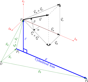 Schematic of cylindrical axis flow angle definitions The cylindrical axis of rotation may correspond to one of the three Cartesian axis directions, as specified by the option X, Y, or Z. The default is X. The user may instead use the AXIS option to specify an arbitrary axis defined by two points. When used with the RTZ_RANGE keyword, point P1=(x1,y1,z1) is used as the origin of the cylindrical coordinate system (a=0). For convenience users will likely want to set this first point to the center of the inflow plane. |
Angles specified with the DIRECTION keyword will override any angles of attack or sideslip specified when setting boundary condition values with the UNIFORM, USURFACE, IJK_RANGE, XYZ_RANGE, RTZ_RANGE, VORTEX, SOLIDBODY, or ROTATESOLID keywords. However, if UNIFORM is used without specifying the flow conditions or the FREESTREAM option is used, then the angles specified with the FREESTREAM keyword will be used and the DIRECTION keyword will have no effect. The DIRECTION keyword also does not affect flow angles in profiles specified with the USERSPEC, USERCHEM, USERKE, or USERCHEMKE keywords.
Only the DIRECTION CYLINDRICAL keyword setting will modify the flow angles that are set when ARBITRARY INFLOW is being used to initialize (or reinitialize) flow conditions within a zone. The reason for this is that the other options are designed for surfaces and may not be appropriate for initializing the interior of the zone.
The DIRECTION option used will remain in effect for all following keywords.
Zone Specification
| ZONE n |
This keyword, which must be specified, identifies the zone for which inflow conditions are being set. For example, if zone 2 is an internal jet, conditions other than freestream may be desired at the inflow to zone 2.
Within the ARBITRARY INFLOW keyword block, the ZONE keyword must come after any relevant "Control Function" keywords (such as STATIC, TOTAL, HOLD_TOTALS, HOLD_CHARACTERISTICS, or DIRECTION) but before any "Condition Specification" keyword for that zone. Incorrect placement of the ZONE keyword will result in the wrong flow conditions being imposed. In addition, the ZONE keyword may only be used to specify one zone at a time, not a range of zones.
Example
The following ARBITRARY INFLOW block specifies that the flow values for pressure and temperature will be treated as total conditions for all subsequent zones. Total conditions are to be held constant at arbitrary inflow surfaces in zones 1 and 2, with M = 0.5, PT = 251.15 psi, and TT = 1167.9 °R. In zone 3, characteristic values are to be held constant at arbitrary inflow surfaces, consistent with the flow conditions given with the FREESTREAM keyword. Though not required, the use of whitespace to indent keywords can help clarify the hierarchy of the intended flow conditions.
   ARBITRARY INFLOW
      TOTAL
      HOLD_TOTALS
         ZONE 1
            UNIFORM 0.5 251.15 1167.9 0.0 0.0
         ZONE 2
            UNIFORM 0.5 251.15 1167.9 0.0 0.0
      HOLD_CHARACTERISTICS
         ZONE 3
            UNIFORM
   ENDINFLOW
Condition Specification
The following keywords may be used to specify the flow condition to be applied on the boundary. The condition specification should always come after the ZONE specification. Interpretation of the flow values is subject to the "Control Functions" described previously.
| FREESTREAM |
This keyword is used to specify that freestream conditions should also be applied at the specified arbitrary inflow boundaries. It is more convenient than having to re-specify the flow values using the other methods listed below. Note that the behavior of this boundary is controlled by the HOLD_TOTALS, HOLD_CHARACTERISTICS, or HOLD_FLOWRATE keywords, whereas freestream boundaries are controlled by HOLD TOTALS or HOLD CHARACTERISTICS without the underscore.
| HOLD_CURRENT |
This keyword is used to specify that the arbitrary inflow conditions should be held at the current values in the solution file. This differs from a FROZEN boundary type in that reversed flow is allowed out of the domain. Unlike some other HOLD options, HOLD_CURRENT does not affect subsequent zones.
| HOLD_MASS mdot |
The HOLD_MASS keyword may be used to specify an incoming mass flow. The required input parameter is:
| mdot | Mass flow desired through the inflow boundary, lbm/sec. |
|---|
HOLD_MASS should only be specified after a ZONE command and after the desired conditions are specified (via UNIFORM, IJK_RANGE, etc.). The specified mass flow will be set for the selected zones. It therefore represents a zonal value, not an aggregate or global value that is shared between zones. Unlike some other HOLD options, HOLD_MASS does not affect subsequent zones. Multiple HOLD_MASS commands may be specified within an arbitrary inflow block, but only one condition may be specified per zone. HOLD_MASS has not yet been implemented for unstructured grids.
HOLD_MASS works by using the HOLD_TOTALS settings, but then adds a uniform total pressure increment to the boundary to achieve the specified mass flow rate. Adjustment of the total pressure increment is done at the same frequency as that specified for outflow MASS FLOW conditions. Note that the total pressure increment is not stored in the .cfl solution file. On restart, the total pressure mass flow increment must be re-converged, disrupting the overall convergence relative to a continuous run. One way to avoid this disruption is to integrate the total pressure of the interim solution and change the .dat input file to specify this total pressure. Otherwise, the total pressure increment should converge rapidly, but the user should run sufficient iterations on restart to ensure a converged solution.
Example
The following ARBITRARY INFLOW block specifies different mass flow conditions in two zones.
   ARBITRARY INFLOW
   TOTAL
   HOLD_TOTALS
   ZONE 1
      UNIFORM 0.2 15.0 530.0 0. 0.
      HOLD_MASS 1.5
   ZONE 2
      UNIFORM 0.2 16.5 900.0 0. 0.
      HOLD_MASS 2.0
   ENDINFLOW
|
UNIFORM [M P T α β [val_k [val_om]]] [sp1 sp2 ... spn] |
This keyword is used to specify uniform flow at arbitrary inflow boundaries, at the flow conditions listed below. If the flow conditions are omitted, those specified with the FREESTREAM keyword are used.
| M | Mach number | ||
|---|---|---|---|
| P | Pressure, psi | ||
| T | Temperature, °R | ||
| α, β | Angles of attack and sideslip, in degrees. See the description of aerodynamic axes. | ||
| sp1, sp2, ..., spn | Species mass fractions. These are required for real gas flows. They must appear on a separate line, and the order for these values must be consistent with the order in which the species are listed with the SPECIES keyword in the CHEMISTRY keyword block. |
Pressure and temperature are static or total, depending on whether STATIC or TOTAL is specified.
For structured grids, when the SST turbulence model is being used (see the TURBULENCE keyword), val_k and val_om may be used to specify inflow turbulence levels. You may specify either val_k, or val_k and val_om, but not val_om by itself. Note that if these values are being specified, the TURBULENCE keyword must come before the ARBITRARY INFLOW keyword block in the input data (.dat) file.
The following options are possible:
| val_k > 0 | The turbulent kinetic energy k and the specific dissipation
rate ω are specified directly, with
ω = val_om (1/sec) The turbulent viscosity νt is then equal to k/ω.
| ||
|---|---|---|---|
| val_k < 0 | The turbulence intensity is set equal to abs(val_k),
expressed as a percentage of the inflow velocity U,
where U is computed from the specified values of M
and T.
Thus, the turbulent kinetic energy is computed as
The turbulent viscosity νt is automatically set equal to 0.001 νl, where νl is the laminar viscosity, and the specific dissipation rate is computed as ω = k/νt.
| ||
| val_om < 0 | The specific dissipation rate ω is set equal to
val_om percent of U/Lref,
where U is computed from the specified values of M
and T, and Lref is the reference length
from the grid (.cgd) file.
Thus
The turbulent viscosity νt is set to the same percentage of the laminar viscosity.
The turbulent kinetic energy is then computed as k = ωνt. |
If inflow turbulence levels are not specified using one of the above options, or if val_k = 0, default values are computed from
Note that
These inflow values will be used to initialize the flow and applied during each cycle update. If the flow exits the boundary at any time during the solution procedure, values from the interior will be extrapolated to that boundary point. Should the flow subsequently re-establish itself as entering the domain, the specified inflow turbulence will once again be applied.
Example
   ARBITRARY INFLOW
      ZONE 1
         UNIFORM 1.1 100. 900. 10. 0.
   ENDINFLOW
| USURFACE [FROZEN] surface M P T α β [sp1 sp2 ... spn] |
This keyword is used with unstructured grids to specify uniform flow at arbitrary inflow surfaces, at the flow conditions listed below. The flow conditions are specified in terms of Mach number, pressure, and temperature. Note that unlike the UNIFORM keyword, the flow conditions must be specified.
| surface | Surface ID number | ||
|---|---|---|---|
| M | Mach number | ||
| P | Pressure, psi | ||
| T | Temperature, °R | ||
| α, β | Angles of attack and sideslip, in degrees. See the description of aerodynamic axes. | ||
| sp1, sp2, ..., spn | Species mass fractions. These are required for real gas flows. The order for these values must be consistent with the order in which the species are listed with the SPECIES keyword in the CHEMISTRY keyword block. Note that unlike the UNIFORM keyword, here the mass fractions are on the same line as the rest of the flow conditions. |
The pressure and temperature listed above may be either static or total, depending on whether STATIC or TOTAL is specified.
The FROZEN option may be specified to freeze the inflow conditions on the surface at the specified values. Note that unlike the FROZEN option available with IJK_RANGE for structured grids, here the values specified with the keyword are used, not those in the .cfl file.
The total number of USURFACE surfaces, and IJK_RANGE, XYZ_RANGE, and RTZ_RANGE regions, is limited to 4000.
Example
   ARBITRARY INFLOW
      ZONE 1
         USURFACE 9 1.1 100. 900. 10. 0.
   ENDINFLOW
|
IJK_RANGE [FROZEN] imin imax jmin jmax kmin kmax \ M P T α β [val_k [val_om]] [sp1 sp2 ... spn] |
For structured grids, this keyword allows specification of inflow conditions over an arbitrary range of i, j, and k indices on any computational boundary plane. The user specifies the minimum and maximum i, j, and k indices which describe the region, followed by the flow conditions to be applied, as follows:
| imin, imax | Minimum and maximum i indices bounding the region | ||
|---|---|---|---|
| jmin, jmax | Minimum and maximum j indices bounding the region | ||
| kmin, kmax | Minimum and maximum k indices bounding the region | ||
| M | Mach number | ||
| P | Pressure, psi | ||
| T | Temperature, °R | ||
| α, β | Angles of attack and sideslip, in degrees. See the description of aerodynamic axes. | ||
| sp1, sp2, ..., spn | Species mass fractions. These are required for real gas flows. They must appear on a separate line, and the order for these values must be consistent with the order in which the species are listed with the SPECIES keyword in the CHEMISTRY keyword block. |
Pressure and temperature are static or total, depending on whether STATIC or TOTAL is specified. There are no defaults for the index ranges.
The FROZEN option may be specified to freeze the inflow conditions over the indicated index range at their current values. Note that for a restart case (i.e., when a .cfl file already exists), the "current values" are those in the .cfl file, not those specified with the IJK_RANGE keyword. For an initial run (i.e., when a .cfl file does not exist), the flow conditions will be frozen at the conditions specified with the IJK_RANGE keyword.
If the SST turbulence model is being used (see the TURBULENCE keyword), val_k and val_om may be used to specify inflow turbulence levels. The various options are described above under the UNIFORM keyword.
A combination of up to 4000 IJK_RANGE, XYZ_RANGE, and RTZ_RANGE regions and (for unstructured grids) USURFACE surfaces may be specified. This is useful when specifying a boundary layer profile at an inflow boundary, or along solid walls during the flowfield initialization process.
| UNSTEADY var_name freq ampl phase |
This keyword allows the user to specify unsteady arbitrary inflow conditions. It must be used with (and follow) the IJK_RANGE keyword for structured grids or the USURFACE keyword for unstructured grids. Up to ten different perturbations to the inflow conditions may be specified and will be superimposed to create unsteadiness centered about the conditions given with the IJK_RANGE or USURFACE keywords.
| var_name | One of the keywords MACH, PRESSURE, TEMPERATURE, ALPHA, BETA, or VELOCITY | ||
|---|---|---|---|
| freq | Frequency of the perturbation in Hertz | ||
| ampl | Amplitude of the perturbation in appropriate variable units | ||
| phase | Phase angle of the perturbation in degrees |
UNSTEADY may only be used when a constant time step is specified with the CFL# keyword, and only for a perfect gas.
Note that you may specify multiple, independent pairs of IJK_RANGE (or USURFACE) and UNSTEADY keywords.
|
XYZ_RANGE [BLEND {XMIN | XMAX}] xmin xmax ymin ymax zmin zmax \ M P T α β [val_k [val_om]] [sp1 sp2 ... spn] |
This keyword is intended for use during the flowfield initialization process, and allows specification of initial conditions in a specified Cartesian bounding box. The user specifies the bounding box coordinates, followed by the flow conditions to be applied, as follows:
| xmin, xmax | Minimum and maximum x coordinates bounding the region | ||
|---|---|---|---|
| ymin, ymax | Minimum and maximum y coordinates bounding the region | ||
| zmin, zmax | Minimum and maximum z coordinates bounding the region | ||
| M | Mach number | ||
| P | Pressure, psi | ||
| T | Temperature, °R | ||
| α, β | Angles of attack and sideslip, in degrees. See the description of aerodynamic axes. | ||
| sp1, sp2, ..., spn | Species mass fractions. These are required for real gas flows. They must appear on a separate line, and the order for these values must be consistent with the order in which the species are listed with the SPECIES keyword in the CHEMISTRY keyword block. |
Pressure and temperature are static or total, depending on whether STATIC or TOTAL is specified. There are no defaults for the bounding box coordinates.
If BLEND XMIN or BLEND XMAX is specified, the initial conditions will smoothly transition from the specified values at xmin to freestream values at xmax, or from the specified values at xmax to freestream values at xmin, respectively. If BLEND is not specified, the initial conditions will be uniform, at the specified values. This option is only available for perfect gas flows.
If the SST turbulence model is being used (see the TURBULENCE keyword), val_k and val_om may be used to specify inflow turbulence levels. The various options are described above under the UNIFORM keyword.
A combination of up to 4000 IJK_RANGE, XYZ_RANGE, and RTZ_RANGE regions and (for unstructured grids) USURFACE surfaces may be specified. This is useful when specifying a boundary layer profile at an inflow boundary, or along solid walls during the flowfield initialization process.
|
RTZ_RANGE [BLEND {ZMIN | ZMAX}] rmin rmax tmin tmax zmin zmax \ M P T α β [val_k [val_om]] [sp1 sp2 ... spn] |
This keyword is analogous to the XYZ_RANGE keyword, but allows the bounding box to be specified in cylindrical coordinates. Note that the z coordinate is along the cylindrical axis, which defaults to the Cartesian x-axis unless the DIRECTION CYLINDRICAL keyword is used. The bounding box coordinates are:
| rmin, rmax | Minimum and maximum r coordinates bounding the region | ||
|---|---|---|---|
| tmin, tmax | Minimum and maximum θ coordinates (in degrees) bounding the region | ||
| zmin, zmax | Minimum and maximum z coordinates bounding the region |
The remaining input is the same as for XYZ_RANGE. Note that when using an arbitrary axis, via the DIRECTION CYLINDRICAL AXIS keyword combination, the full 360 degree range will be used regardless of the θ values entered.
If BLEND ZMIN or BLEND ZMAX is specified, the initial conditions will smoothly transition from the specified values at zmin to freestream values at zmax, or from the specified values at zmax to freestream values at zmin, respectively. If BLEND is not specified, the initial conditions will be uniform, at the specified values.
Multiple RTZ_RANGE keywords may be used to overlay flow conditions onto portions of the inflow region. Different DIRECTION CYLINDRICAL specifications may be made for each.
Example 1
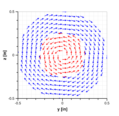
The following ARBITRARY INFLOW block specifies an inflow plane at x=0 with two coaxial counterswirling regions and no swirl in the corners.
   ARBITRARY INFLOW
     TOTAL
     HOLD_TOTALS
     DIRECTION CYLINDRICAL AXIS CENTER 0.0 0.0 0.0 AXIS_POINT 5.0 0.0 0.0
     ZONE 1
     UNIFORM                                        0.10  15.0  540.0   0.0 0.0
     RTZ_RANGE 0.00 0.50  0.00 360.00  -0.05 0.05   0.10  15.0  530.0 -45.0 0.0
     RTZ_RANGE 0.00 0.25  0.00 360.00  -0.05 0.05   0.10  15.0  540.0  45.0 0.0
   /           <-- r -->  <--- t --->  <--- z -->      M    Pt     Tt   alp bet
   ENDINFLOW
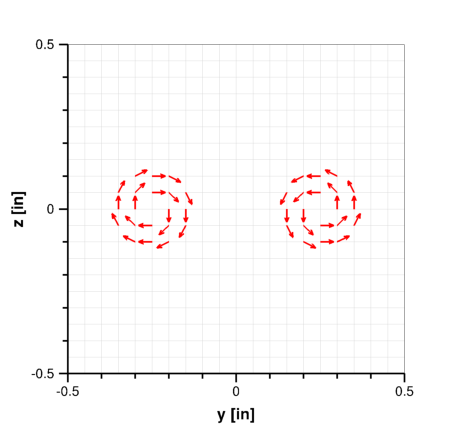
Example 2
This example specifies an ARBITRARY INFLOW plane at x=0 with a pair of counterrotating vortices. Note that the first DIRECTION CYLINDRICAL keyword specifies the default axis for the zone, and the other specifies a different axis for the second RTZ_RANGE.
   ARBITRARY INFLOW
     TOTAL
     HOLD_TOTALS

     DIRECTION CYLINDRICAL AXIS CENTER 0.0 -0.25 0.0 AXIS_POINT 5.0 -0.25 0.0
     ZONE 1
     UNIFORM                                        0.10  15.0  530.0   0.0 0.0
     RTZ_RANGE 0.00 0.13  0.00 360.00  -0.05 0.05   0.10  15.0  540.0 -45.0 0.0

     DIRECTION CYLINDRICAL AXIS CENTER 0.0 +0.25 0.0 AXIS_POINT 5.0 +0.25 0.0
     ZONE 1
     RTZ_RANGE 0.00 0.13  0.00 360.00  -0.05 0.05   0.10  15.0  540.0  45.0 0.0
   /           <-- r -->  <-- t  --->  <--- z -->      M    Pt     Tt   alp bet
   ENDINFLOW
|
TURBULENT [INFLOW] [MAGNITUDE] vpmag {FPS|MEAN|PERCENT} [SIZE nsiz] \ [SEED seed] [PEAK_K kpeak [PER_FOOT]] [BL_HEIGHT blhgt] |
For structured grids, this keyword allows the user to specify an unsteady pseudo-turbulent flow at the inflow boundary. It currently only affects the boundary conditions for the mean flow, not the turbulence model equations. Since the mean velocity field typically carries the majority of the energy, this isn't considered critical.
| vpmag | Magnitude of the turbulent intensity (i.e., turbulent velocity fluctuations) specified in either feet per second (FPS), fraction of the mean flow velocity (MEAN), or percent of the mean flow velocity (PERCENT). The intensity will be the same in each coordinate direction. | ||
|---|---|---|---|
| nsiz | Number of grid points on each side of the "box" of pseudo-turbulent inflow. I.e., the box will contain nsiz × nsiz points for 2-D cases, and nsiz × nsiz × nsiz points for 3-D cases. The default value is 64. | ||
| seed | A random number seed, used to ensure repeatability of a given run. The default value is 987.0. | ||
| kpeak | The wave number (based on the box size unless PER_FOOT is specified) where the energy spectrum is to peak. The default value is 8.0. | ||
| blhgt | The height, in feet, of the incoming boundary layer. The turbulence at the inflow boundary will be scaled in this region to account for the presence of the boundary layer. The default is Lbox/10, where Lbox is the length of a side of the cube bounding the arbitrary inflow boundary. |
When the TURBULENT keyword is used, total conditions must be held constant, and HOLD_TOTALS is automatically applied.
|
{VORTEX | SOLIDBODY | ROTATESOLID} Mn P T α β xc yc zc \ {dw1 | dw1 dw2 dw3} |
These keywords may be used to specify uniform inflow conditions with free-vortex or solid-body rotation superimposed. They are only valid for a perfect gas, and cannot be used with CHEMISTRY. Solid-body rotation may be specified on any arbitrary inflow boundary. For free-vortex rotation, however, the arbitrary inflow boundary must be a x-, y-, or z-constant plane, and the center of rotation must lie on that plane.
| Mn | Normal component of Mach number | ||
|---|---|---|---|
| P | Pressure, psi | ||
| T | Temperature, °R | ||
| α, β | Average angles of attack and sideslip, in degrees. See the description of aerodynamic axes. | ||
| xc, yc, zc | Center of rotation in physical coordinates |
For VORTEX,
| dw1 | Vortex strength. (See the ACTUATOR keyword.) |
|---|
For SOLIDBODY and ROTATESOLID,
| dw1, dw2, dw3 | x, y, and z components of the rotation rate vector (degrees/sec). (Note: prior to Wind-US 2.184 these were in radians per second. Input data files using these keywords with earlier versions of Wind-US will need to be changed if used with Wind-US 2.184 or later.) |
|---|
The rotational velocity components are added in such a way that total pressure and total temperature are held constant at the inflow boundary. Thus, the TOTAL option should always be used for this mode, since with the STATIC option the computed static pressure and temperature at the inflow boundary may differ from the specified values.
For calculations in a rotating reference frame (see the ROTATE keyword):
For both free-vortex and solid-body rotation, the flowfield must already be initialized. (See the Flowfield Initialization section.) I.e., there must be a pre-existing .cfl file. The VORTEX, SOLIDBODY, and ROTATESOLID options cannot be used during a "cold" start.
Special Capabilities for Structured Grids
The following arbitrary inflow keywords are only valid for structured grids, and are only applied at the i = 1 computational plane.
|
USERSPEC fs bl1 bl2 npts y1 M P T α β y2 M P T α β ... yn M P T α β |
This option allows the user to specify a 1-D profile normal to the surface, translated through some buttline range, below the vehicle. These conditions will be set last and thus the data will overwrite UNIFORM conditions over the range of interest.
| fs | Fuselage station of the profile (to be checked against the grid i = 1 fuselage station) | ||
|---|---|---|---|
| bl1, bl2 | Minimum and maximum buttline over which to translate the profile | ||
| npts | Number of points defining the profile | ||
| y1 - yn | Normal distance from the wall | ||
| M | Mach number | ||
| P | Pressure, psi | ||
| T | Temperature, °R | ||
| α, β | Angles of attack and sideslip, in degrees. See the description of aerodynamic axes. |
The pressure and temperature may be the total or static conditions, depending upon the current setting of the TOTAL/STATIC keyword. If neither STATIC nor TOTAL have been specified under ARBITRARY INFLOW, then the existing switch from the global input parameters is used (default: TOTAL).
One profile can be specified for each zone. There can be 100 points in each profile. The normal distance is always assumed to be from j = 1 (the reference wall is assumed to be at j = 1). bl1 is the minimum buttline and bl2 is the maximum buttline.
By default, USERSPEC only specifies conditions below a vehicle. That is, the wall (j = 1) must be above (higher y) the interior grid points. TEST 157 specifies that all points within the specified buttline range will be affected, above and below the vehicle. This should be the default, but isn't.
See Also: TEST 157
|
USERCHEM fs bl1 bl2 npts y1 M P T α β sp1 sp2 ... spn y2 M P T α β sp1 sp2 ... spn ... yn M P T α β sp1 sp2 ... spn |
The USERCHEM option is identical to the USERSPEC option, except that chemistry species mass fractions sp1, sp2, ..., spn are added. The order for the mass fractions must be consistent with the order in which the species are listed with the SPECIES keyword in the CHEMISTRY keyword block. Test options can then be set to model the mixing of gas streams which have different chemical compositions. At this time, only mixing can be modeled. The gas streams cannot chemically react.
Note: Only the STATIC input mode is available for chemistry.
Part of an example USERCHEM input block follows. The file sets up a rectangular jet where the jet composition is a mixture of O2, CO2, H2O, NO2, and N2.
   ARBITRARY INFLOW
      ZONE 1
      USERCHEM 0.0 -10.0 10.0 6
        0.0   0.3  5.70   433.1  0.0  0.0
            0.234  0.0    0.0    0.0  0.766
      123.05  0.3  5.70   433.1  0.0  0.0
            0.234  0.0    0.0    0.0  0.766
      123.05  1.8  5.66  1940.0  0.0  0.0
            0.096  0.120  0.048  0.0  0.736
      133.75  1.8  5.66  1940.0  0.0  0.0
            0.096  0.120  0.048  0.0  0.736
      133.75  0.3  5.70   433.1  0.0  0.0
            0.234  0.0    0.0    0.0  0.766
      257.0   0.3  5.70   433.1  0.0  0.0
            0.234  0.0    0.0    0.0  0.766
   ENDINFLOW
   TEST 157 1     USERSPEC ABOVE AND BELOW VEHICLE
|
USERKE fs bl1 bl2 npts y1 M P T α β val_k [val_om] y2 M P T α β val_k [val_om] ... yn M P T α β val_k [val_om] |
The USERKE option is identical to the USERSPEC option, except that the values val_k and val_om are added to specify inflow turbulence levels when the SST turbulence model is being used. The various options are described above under the UNIFORM keyword.
|
USERCHEMKE fs bl1 bl2 npts y1 M P T α β sp1 sp2 ... spn val_k [val_om] y2 M P T α β sp1 sp2 ... spn val_k [val_om] ... yn M P T α β sp1 sp2 ... spn val_k [val_om] |
The USERCHEMKE option is identical to the USERCHEM option, except that the values val_k and val_om are added to specify inflow turbulence levels when the SST turbulence model is being used. The various options are described above under the UNIFORM keyword.
See Also: EXTRAPOLATE, INITIALIZE, MASS FLOW, REINITIALIZE, ROTATE, TURBULENCE
Last updated 30 Sep 2016