
|
BLOW {MASS region mdot Tinj [STATIC|TOTAL] \ angle_inc [{ABOUT_Z | ABOUT_NORMAL | ABOUT_BODY} [angle_azi]] | \ PLENUM region Pt T angle | \ SURFACE region {UNSTEADY | Pt Tt | Ptmax Tt PRATIO Pratio} \ angle_inc [{ABOUT_Z | ABOUT_NORMAL | ABOUT_BODY} [angle_azi]] | \ WALL region | \ VALVE region Pt Tt angle} [BLOW SPECIES_FRACTIONS region sp1 sp2 ... spn] [BLOW FORCING region {MASS|VELOCITY} amp freq phase] |
Porous wall cooling over a selected region can be simulated using this keyword. The region must be identified as a bleed region in the grid file. This option is intended for mass inflow only (i.e., Pt > local Ps). It won't work well for grids that are skewed at the wall, resulting in blowing mass flow errors.
Blowing may also be modeled using the first two forms of the BLEED keyword (i.e., BLEED and BLEED POROSITY).
The definition of the blowing direction is general enough that a blowing region on the upper and/or lower surface of a wing will be treated consistently with a single specification. However, one should avoid specifying a blowing region in more severe cases, such as the normal part of a backward-facing step, where the surface normal is purely in the x direction.
Except for BLOW MASS, BLOW SURFACE, and BLOW
VALVE, blowing is only allowed for perfect gases, for both
structured and unstructured grids.
In addition, with unstructured grids blowing is only allowed with
non-rotating grids.
With unstructured grids, the blowing boundary condition is applied at
the cell faces, but the flow field values written to the .cfl
file for post-processing are at the nodes.
The results may thus be slightly different around the edges of the
blowing region with structured and unstructured grids.
|
BLOW MASS region mdot Tinj [STATIC|TOTAL] \ angle_inc [{ABOUT_Z | ABOUT_NORMAL | ABOUT_BODY} [angle_azi]] [BLOW SPECIES_FRACTIONS region sp1 sp2 ... spn] [BLOW FORCING region {MASS|VELOCITY} amp freq phase] |
| region | Bleed region number from .cgd file | ||
|---|---|---|---|
| mdot | Injected mass flow in region region (lbm/sec) | ||
| Tinj | Temperature of injected flow (°R). Either static or total temperature may be specified, as indicated by the optional choice of STATIC or TOTAL. (However, TOTAL may not be used when VELOCITY is used with BLOW FORCING, or for non-perfect gases.) The default is STATIC. | ||
| angle_inc | Blowing inclination angle, φ (degrees). Must be greater than 0.0. | ||
| angle_azi | Blowing azimuthal angle, ψ (degrees). The default is 0.0. | ||
| sp1 sp2 ... spn | Mass fractions of injected species. The default values are those specified in the CHEMISTRY keyword block. |
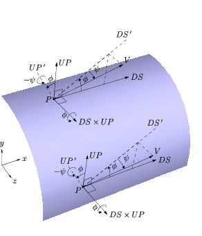
The blowing direction is set by the input inclination and azimuthal angles. There are three methods for specifying these angles: ABOUT_BODY, ABOUT_NORMAL, and ABOUT_Z. If neither method is specified, ABOUT_Z is assumed, and angle_azi will have its default value of 0.0.
| 
|
| (a) Right circular cylinder. | (b) Right circular cone. |
|---|
If ABOUT_BODY is specified, the flow direction is based on the body axes, independent of the local surface normal. Specifically, the inclination angle (φ) is a rotation about the DS×UP direction, starting from the "downstream" axis (DS) and moving toward the "up" axis (UP). The azimuthal angle (ψ) is then a rotation about the −UP' direction, where UP' is the orientation of the UP axis if it was rotated by φ. The vector components are given by:
| V ⋅ DS | = | V cos ψ cos φ |
| V ⋅ UP | = | V cos ψ sin φ |
| V ⋅ (DS×UP) | = | V sin ψ |
| 
|
| (a) Right circular cylinder. | (b) Right circular cone. |
|---|
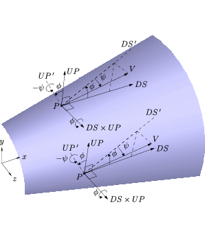
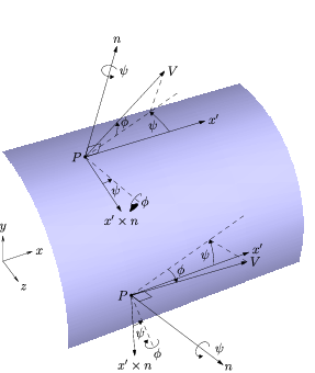
If ABOUT_NORMAL is specified, the blowing direction is computed based on the local surface normal direction (n). Let x' designate the projection of the x-axis onto the surface defined by n.
| V ⋅ x' | = | V cos φ cos ψ |
| V ⋅ n | = | V sin φ |
| V ⋅ (x'×n) | = | −V cos φ sin ψ |
| 
|
| (a) Right circular cylinder. | (b) Right circular cone. |
|---|
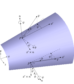
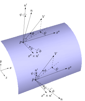
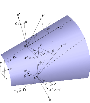
If ABOUT_Z is specified, the blowing direction is computed based on the projection of the local surface normal onto a z-constant plane. Let n represent the local normal direction of the three-dimensional surface, and let n' be the projection of the surface normal onto the xy-plane.
| V ⋅ x'' | = | V cos φ cos ψ |
| V ⋅ n' | = | V sin φ |
| V ⋅ (x''×n') | = | −V cos φ sin ψ |
For finite-rate chemistry, when BLOW SPECIES_FRACTIONS is specified the mass fractions should be specified in the same order as the species in the chemistry data (.chm) file. However, if the species have been re-ordered using the SPECIES keyword in the CHEMISTRY keyword block, and the BLOW SPECIES_FRACTIONS keyword comes after the CHEMISTRY keyword block in the input data (.dat) file, then the mass fractions should be specified in the new species order.
BLOW FORCING may be used with this blowing mode to add an
oscillatory component to the blowing velocity.
The added blowing is specified as either a mass flow or velocity,
depending on the choice of MASS or VELOCITY.
(If VELOCITY is used, the static temperature must be specified
with the BLOW keyword.)
The direction of the added blowing will be the same as the mean blowing,
as determined by angle_inc and angle_azi.
| region | Bleed region number from .cgd file | ||
|---|---|---|---|
| amp | Amplitude of the oscillation for the added blowing (lbm/sec for MASS, ft/sec for VELOCITY) | ||
| freq | Frequency of the oscillation (deg/sec) | ||
| phase | Phase offset of the oscillation (deg) |
|
BLOW PLENUM region Pt T angle [BLOW FORCING region {MASS|VELOCITY} amp freq phase] |
| region | Bleed region number from .cgd file | ||
|---|---|---|---|
| Pt | Plenum total pressure (psi) | ||
| T | Plenum static temperature (°R) | ||
| angle | Blowing angle relative to xy-plane (degrees) |
If the flowfield static pressure Ps becomes greater than the plenum total pressure Pt, the plenum total pressure will be automatically increased to 1.005 Ps to maintain a blowing boundary condition. Setting TEST 52 will notify the user when this occurs.
BLOW FORCING may be used with this blowing mode to add an oscillatory component to the blowing velocity. The added blowing is specified as either a mass flow or velocity, depending on the choice of MASS or VELOCITY. The direction of the added blowing will be the same as the mean blowing, as determined by angle. The input parameters are the same as when BLOW FORCING is used with BLOW MASS, described above.
This blowing mode may only be used with a perfect gas.
|
BLOW SURFACE region {UNSTEADY | Pt Tt | Ptmax Tt PRATIO Pratio} \ angle_inc [{ABOUT_Z | ABOUT_NORMAL | ABOUT_BODY} [angle_azi]] [BLOW FORCING region MASS amp freq phase] |
| region | Bleed region number from .cgd file | ||
|---|---|---|---|
| Pt | Plenum total pressure (psi) | ||
| Tt | Plenum total temperature (°R) | ||
| Ptmax | Maximum plenum total pressure (psi) | ||
| Pratio | Ratio of plenum total pressure to passage static pressure. Must be > 1. | ||
| angle_inc | Blowing inclination angle (degrees). Must be > 0. | ||
| angle_azi | Blowing azimuthal angle (degrees). The default is 0.0. |
If UNSTEADY is specified, unsteady periodic plenum conditions are applied. The plenum conditions over one period must be specified in a table immediately following the BLOW SURFACE keyword, with the following format:
   PROFILE npts
   time(1)    press(1)    temp(1)
   time(2)    press(2)    temp(2)
   ...
   time(npts) press(npts) temp(npts)
where npts is the number of points in the profile, time is time in seconds, press is total pressure in psi, temp is total temperature in ° R.
If the PRATIO option is specified, then the plenum total pressure is computed from the local static pressure and specified pressure ratio, Pratio. However, this computed value is not allowed to exceed the prescribed Ptmax.
With BLOW SURFACE, blowing will occur whenever the local flowfield static pressure is less than the specified plenum total pressure. If the flowfield static pressure is greater than the plenum total pressure, the velocity normal to the wall at that point is set to zero (i.e., a solid wall with no blowing or bleed). Unlike the BLOW VALVE capability, with BLOW SURFACE blowing is turned on or off locally, on a point-by-point basis.
The blowing velocity is also constrained to subsonic values.
The blowing direction is set by the input inclination and azimuthal angles. The angles are defined in the same way as when BLOW MASS is used to specify a constant blowing mass flow.
The BLOW SURFACE keyword may not be used for multi-species flows, but may be used with Liu-Vinokur equilibrium air chemistry.
If the TEST 195 option is set, a message will be written in the list output (.lis) file whenever the blowing is turned off because the flowfield static pressure is too large. Note, however, that this is a five-line message written for each iteration and each "closed" node, and could cause the .lis file to become very large very quickly.
BLOW FORCING may be used with this blowing mode to add an
oscillatory component to the blowing velocity.
Note that when BLOW FORCING is used with BLOW SURFACE,
the added blowing must specified as a mass flow.
The VELOCITY option is not available.
The direction of the added blowing will be the same as the mean blowing,
as determined by angle_inc and angle_azi.
The input parameters are the same as when BLOW FORCING is used
with BLOW MASS, described
above.
[When both BLOW FORCING and UNSTEADY are used with
BLOW SURFACE, the forcing is applied after the unsteady plenum
conditions.
Note, though, that using these together probably doesn't make sense.]
| BLOW WALL region |
| region | Bleed region number from .cgd file |
|---|
This keyword may be used to explicitly turn blowing off in a specific
region, and to treat the boundary as a viscous solid wall.
|
BLOW VALVE region Pt Tt angle [BLOW SPECIES_FRACTIONS region sp1 sp2 ... spn] |
| region | Bleed region number from .cgd file | ||
|---|---|---|---|
| Pt | Plenum total pressure (psi) | ||
| Tt | Plenum total temperature (°R) | ||
| angle | Blowing angle relative to xy-plane (degrees) | ||
| sp1 sp2 ... spn | Mass fractions of injected species. The default values are those specified in the CHEMISTRY keyword block. |
If the flowfield static pressure Ps becomes greater than the plenum total pressure Pt at any point within the blowing region, blowing will be shut off for the entire region, and the surface will be treated as a solid wall. A *VLV* line is written to the list output (.lis) file whenever the valve changes status.
For finite-rate chemistry, when BLOW SPECIES_FRACTIONS is specified the mass fractions should be specified in the same order as the species in the chemistry data (.chm) file. However, if the species have been re-ordered using the SPECIES keyword in the CHEMISTRY keyword block, and the BLOW SPECIES_FRACTIONS keyword comes after the CHEMISTRY keyword block in the input data (.dat) file, then the mass fractions should be specified in the new species order.
With BLOW VALVE, the blowing region may extend to more than a boundary surface, and may also be split between zones. Note, however, that when a blowing region is split between multiple processors, the separate sub-regions act independently until the end of a cycle. If the flowfield static pressure grows large enough in one sub-region to close the valve but not in the other sub-region(s), the valve will close for the first sub-region, but not on the others until the end of the cycle. The reverse situation (i.e., opening a closed valve) may also occur. This may be prevented by running one iteration per cycle; as a practical matter, it is not expected to cause problems with the default of five iterations per cycle.
See Also: BLEED, TEST 16, TEST 46, TEST 52, TEST 67, TEST 178, TEST 195
Last updated 1 Apr 2016