
|
BLEED {MASS region mdot | POROSITY region pplen por [dis] | \ EMPIRICAL region mode blv1 blv2 blv3 blv4 | \ FORCING region amp freq phase | WALL region [TEMPERATURE temp] | \ AEDC region dstar por aspect} |
|
BLEED {MASS region mdot | POROSITY region pplen por dis | \ FORCING region amp freq phase | WALL region} [TEMPERATURE temp] |
The effect of bleed on the flow can be modeled, if bleed regions were identified in the grid file. The parameters discussed below identify the bleed rate for each region, for a specific solution. If a bleed region is not named in this file, its bleed rate is set to zero.
There are several possible bleed modes available. Unless noted otherwise, the keywords apply to both structured and unstructured grids.
Bleed is only allowed for perfect gases, for both structured and
unstructured grids.
With unstructured grids, the bleed boundary condition is applied
at the cell faces, but the flow field values written to the .cfl
file for post-processing are at the nodes.
The results may thus be slightly different around the edges of the
bleed region with structured and unstructured grids.
| BLEED MASS region mdot |
| region | Bleed region number from .cgd file | ||
|---|---|---|---|
| mdot | Normalized bleed flow rate |
mdot can also be thought of as the mass flow ratio for the bleed
region.
The actual bleed mass flow is calculated as
The bleed velocity will automatically be limited to Mach 1.
Although this is intended as a bleed model, it can also be used for
blowing by setting mdot to a negative value.
| BLEED POROSITY region pplen por dis |
[There are some questions about the coding for the porous bleed model that need to be resolved. This model should be therefore used with caution.]
| region | Bleed region number from .cgd file | ||
|---|---|---|---|
| pplen | Back pressure pplen, in psia | ||
| por | Porosity | ||
| dis | Discharge coefficient; may be defaulted for structured grids |
With this model, the velocity at the wall will be computed from the local pressure p in the flow field, and the specified back pressure pplen. If p > pplen, the flow will be out of the computational domain (i.e., bleed). If p < pplen, the flow will be into the computational domain (i.e., blowing).
For unstructured grids, the discharge coefficient must be specified.
For structured grids, however, it may be omitted.
In this case, for bleed a default value is computed from the specified
back pressure and the local flow conditions, using the empirically-based
method of Dittrich and Graves
[Dittrich, Ralph T., and Graves, Charles C. (1956) "Discharge
Coefficients for Combustor-Liner Air-Entry Holes", NACA TN 3663].
For blowing, the default value for the discharge coefficient is 0.6.
| BLEED EMPIRICAL region mode blv1 blv2 blv3 blv4 |
This keyword specifies use of an empirical bleed model that allows
the bleed mass flow rate to vary in response to local flow conditions.
The input parameter region is the bleed region number from
the .cgd file.
The input data for the bleed model is given by the values of
blv1 through blv4.
Various combinations of values may be specified, depending on the
mode, as described below.
Modes 1, 2 and 8 are only available for structured grids.
| mode | blv1 | blv2 | blv3 | blv4 | Description | ||||||
|---|---|---|---|---|---|---|---|---|---|---|---|
| 1 | pplen | Porosity | qsmode | Nbl | Mayer-Paynter model with boundary layer edge specified. | ||||||
| 2 | pplen | Porosity | qsmode | Mayer-Paynter model with boundary layer edge assumed at the grid index midpoint. | |||||||
| 3 | pplen | Porosity | qsmode | M | Mayer-Paynter model with boundary layer edge Mach number specified. | ||||||
| 4 | Qsonic | Porosity | M | Mayer-Paynter model with Qsonic and edge Mach number specified | |||||||
| 5 | pplen | Porosity | Slater model with specified plenum pressure. | ||||||||
| 6 | pexit | Porosity | Cdis | Aexit | Slater model with fixed bleed plenum exit area and pressure. | ||||||
| 7 | pplen | Porosity | mbleed | Slater model with specified mass flux. | |||||||
| 8 | pplen | Porosity | Aexit | Nbl | Bunnag model. (Under development) |
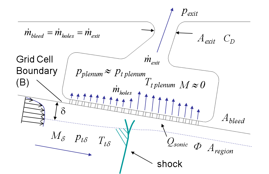
The input parameters are illustrated in the figure below
and can be described as follows:
Aexit is the bleed exit area,
Cdis is the bleed exit discharge coefficient,
M is the local Mach number at the edge of the boundary layer,
mbleed is the actual bleed flow rate,
Nbl is the number of grid points in the boundary layer,
Qsonic is the sonic mass flow coefficient (described below),
pexit is the bleed exit static pressure,
and
pplen is the bleed plenum static pressure.
The parameter qsmode is an integer defining how
Qsonic is to be computed.
| qsmode | Meaning | ||
|---|---|---|---|
| 1 | Set Qsonic = 1 | ||
| 2 | Compute Qsonic for 90° holes | ||
| 3 | Compute Qsonic for 20° holes | ||
| 4 | Compute Qsonic for 90° holes using the Qsonic-B formulation |
Mayer-Paynter Model
In the Mayer-Paynter model [Mayer, D. W. and Paynter, G. C. (1994) "Boundary Conditions for Unsteady Supersonic Inlet Analyses," AIAA Journal, Vol. 32, No. 6, pp. 1200-1206], the bleed flow rate is determined from local solution values at the edge of the boundary layer.
Given the local boundary layer edge Mach number, the freestream total conditions are approximated from the local boundary wall values (B).
The actual mass flow rate through the bleed holes is calculated from
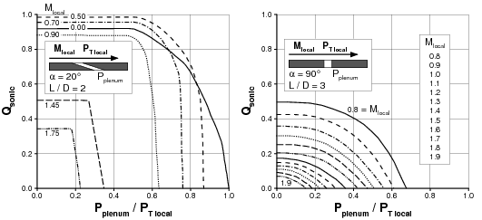
Qsonic is a function of the bleed hole angle α,
the local Mach number M, and the ratio of the plenum pressure
pplen to the local total pressure pT.
The functional relationship is in the form of tabulated experimental
data for circular bleed holes at angles of 20° and 90°.
The 20° data were taken by McLafferty and Ranard
[McLafferty, G., and Ranard, E. (1958) "Pressure Losses and Flow
Coefficients of Slanted Perforations Discharging from Within a
Simulated Supersonic Inlet," United Aircraft Corporation,
Report R-0920-1, Dec. 1958], and the 90° data were taken by
Syberg and Hickox [Syberg, J. and Hickox, T. E. (1972) "Design of a
Bleed System for a Mach 3.5 Inlet," NASA CR-2187, Sept. 1972].
The data are contained in the figure below.
Using the relations above, the local average wall bleed velocity can be computed from
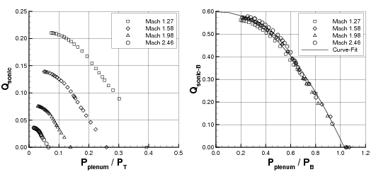
Slater Model
In the Slater model [Slater, J. W., "Improvements in Modeling 90° Bleed Holes for Supersonic Inlets," NASA TM-2009-215597 / AIAA Paper 2009-0710, June 2009], the bleed flow rate is determined from local solution values at the bleed boundary surface (B). This is accomplished by rescaling the terms used in the Mayer-Paynter model to remove the freestream Mach number sensitivity.
The actual mass flow rate through the bleed holes is calculated from
Using these relations, the local average wall bleed velocity can be computed from
For qsmode=6, the plenum pressure is not prescribed. Instead, it is determined assuming a fixed bleed plenum exit area and pressure. The bleed flow rate must match that at the bleed exit, which is computed from an ideal flow rate and the prescribed discharge coefficient.
For qsmode=7, an initial plenum pressure is
prescribed. After that, the plenum pressure is adjusted until
mbleed meets the prescribed mass flow rate.
A positive flow rate means that fluid is exiting the domain.
| BLEED FORCING region amp freq phase |
This mode allows an oscillating normal velocity bleed boundary condition
to be specified.
| region | Bleed region number from .cgd file | ||
|---|---|---|---|
| amp | Amplitude of the normal velocity oscillation (ft/sec) | ||
| freq | Frequency of the oscillation (Hz) | ||
| phase | Phase offset of the oscillation (deg) |
BLEED FORCING was designed to be used on its own, independently
of the other bleed modes.
However, when BLEED FORCING is used in the same bleed region as
another BLEED keyword, the specified oscillatory bleed velocity
will be added to the bleed velocity computed for the other bleed mode.
| BLEED WALL region [TEMPERATURE temp] |
| region | Bleed region number from .cgd file | ||
|---|---|---|---|
| temp | Wall temperature (°R) |
This keyword may be used to explicitly turn bleed off in a specific bleed
region, and to treat the boundary as a viscous solid wall.
| BLEED AEDC region dstar por aspect |
| region | Bleed region number from .cgd file | ||
|---|---|---|---|
| dstar | Displacement thickness at start of bleed region (in) | ||
| por | Porosity | ||
| aspect | Bleed hole aspect ratio (i.e., ratio of bleed hole diameter to wall thickness) |
This bleed mode is only available for structured grids.
When the AEDC keyword is specified, the bleed region uses the AEDC wind tunnel wall correction correlations. This model, based on the work of Martin, Sickles, and Stanley [Martin, F. W., Sickles, W. L., and Stanley, S. A., "Transonic Wind Tunnel Wall Interference Analysis for the Space Shuttle Launch Vehicle," AIAA Paper 93-0420], is hardwired for AEDC wind tunnels, and is not intended for general use. It assumes the following:
See Also: BLOW, MASS FLOW, TEST 46, TEST 67
Last updated 1 Apr 2016