
Selection of the Modular Aerodynamic Design Computational Analysis Process (MADCAP) "View" menu item produces the drop down menu shown below.
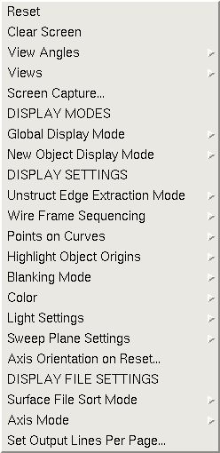
There are nineteen selections under the View menu. They are:
Help on these submenus is available below.
Selection of the "Reset" submenu causes the main graphics display to be resized to fill the main graphics window, at the default axis orientation.
The associated text command is:
view reset
Selection of the "Clear Screen" submenu causes the main graphics display to be cleared of all displayed objects. All data is erased, but the viewing transformation remains unchanged. The graphics scale factor will be determined by sizing the next displayed object to fill the graphics window.
The associated text command is:
view clear
Selection of the "View Angles" submenu causes the following pullout menu to be displayed.
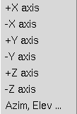
This menu option is used to specify a viewing direction either along one of the principal axes or by providing azimuth and elevation viewing angles.
If a direction along one of the principal axes is selected, the graphics display will be modified such that the selected axis points into the screen. The screen direction for the remaining positive axes will depend on the default (reset) axis orientation, as set by the Axis Orientation on Reset function.
If the "Azim, Elev" menu item is selected, the following window is displayed.
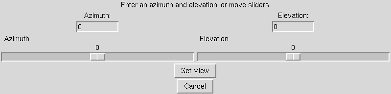
The user may either type elevation and azimuth angles to move the viewpoint to, or move the sliders to modify the values. These viewpoint transformations are relative to the default (reset) axis orientation, as set by the Axis Orientation on Reset function. The azimuthal rotation is performed first, followed by the elevation rotation. Remember that these angles are rotating the viewpoint, not the geometry itself.
Releasing the mouse over the desired principal axis, or choosing the "OK" button on the elevation, azimuth input window will cause the display to be redrawn in the specified orientation.
The associated text command is:
   view angle {+xaxis | -xaxis | +yaxis |-yaxis | +zaxis | -zaxis | \
      azimelev azimuth elevation}
Selection of the "Views" submenu causes the following pulldown menu to be displayed.

If a viewing transformation has been created which the user may desire to use again in the future, it may be saved by selecting the "Save ..." menu option. This causes the following window to be displayed.
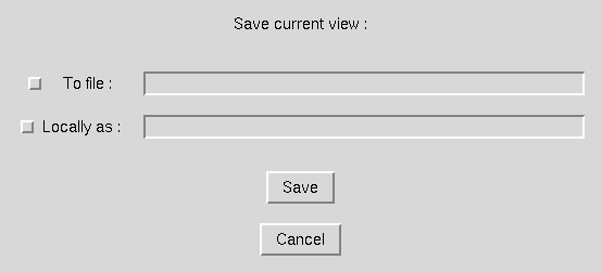
Views may be saved either to file or within a MADCAP session as a named view, or both. To save to file, the user must select the checkbutton labeled "To file", and enter the name of a file to store the transformation in in the entry box. To save locally, select the checkbutton labeled "Locally as", and enter a name for the view in the entry box. A saved view only contains the viewing transformation matrix - it does not maintain a list of displayed surfaces or display modes. Selecting the "OK" button will cause the current view to be saved. To escape with no action being taken, select the "Cancel" button.
If the "Restore ..." menu option is selected, the following window is displayed.
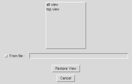
The list box at the top of this window contains the names of all views saved locally within this MADCAP session. To restore a view, the user must either select a name from this list or highlight the "From file" check box and enter the name of a file containing a previously saved viewing matrix. After either selecting a local name or a file name, selecting the "Restore View" button will cause the graphics window to be redrawn with the specified viewing transformation. To exit with no action being taken, select the "Cancel" button.
If the "Delete ..." menu option is selected, the following window is displayed.
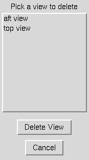
This window contains a list of all named views in a given MADCAP session. There is a finite limit (currently 20) to the number of views that may be saved locally within a given session. If this maximum is reached, and the user needs to save a new view, a previously saved view must be deleted. This can be done by selecting a view name from the displayed list in this window, and then picking the "Delete View" button. To exit with no action being taken, select the"Cancel" button.
The associated text commands are:
   view save {file filename | name viewname}
   view restore {file filename | name viewname}
   view delete name viewname
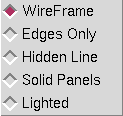
Selection of the "Global Display Mode" submenu causes the following pulldown menu to be displayed.
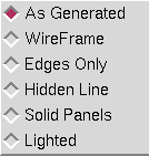
The Global Display Mode determines the style in which all geometry displayed in the graphics window is drawn. The Global Display Mode overrides the Object Display Mode attribute which each drawn entity is assigned based on the current New Object Display Mode setting. If the "As Generated" option is selected, the assigned display mode attribute is used, and each object is drawn in its own style. If any of the other options is selected, the entire display is drawn in that mode.
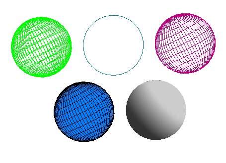
"Wireframe" mode draws objects as see-through wire meshes. "Edges Only" mode draws only the outlines of objects, and results in the fastest real-time rotations. The remaining modes, "Hidden Line", "Solid Panels", and "Lighted", all cause objects closer to the viewer to fully obscure objects behind them. In Hidden Line mode, the grid is drawn just as in Wireframe mode, but the cells are filled in the background color such that hidden lines are removed. In Solid Panels mode, the grid is drawn in the foreground color (typically white), and the cells are filled in the assigned surface color. In Lighted mode, no grid lines are seen and the object is drawn as a solid body illuminated by a light source. The color of the solid body is set under the Color submenu, and the light source location is manipulated under the Light Settings submenu. The images below show a sphere drawn in each of the possible display modes.
Releasing the left mouse button over the desired Global Display Mode will cause that radiobutton to be set, and the graphics display will be redrawn as specified.
The associated text command is:
view mode {asgenerated | wireframe | edges | hidden | solid | lighted}
Selection of the "New Object Display Mode" submenu causes the following pulldown menu to be displayed.
The New Object Display Mode determines the style in which all future objects are displayed. Objects maintain an association with the display mode in which they are originally drawn. Thus, changing the New Object Display Mode has no effect on the current graphics display, but only on objects drawn after a selection has been made. By changing the New Object Display Mode, a mixture of drawing styles may be used at the same time in the display (as long as the "As Generated" option is set in the Global Display Mode). The selected mode stays in effect until changed again. The initial default New Object Display Mode is Wireframe.
If new objects are being drawn in a mode other than the one set, check to ensure that the style is not being overridden by a Global Display Mode. Even if the Global Display Mode is set to something other than "As Generated", the object attribute will be assigned to the current "New Object Display Mode", not to the Global Display Mode.
"Wireframe" mode draws objects as see-through wire meshes. "Edges Only" mode draws only the outlines of objects, and results in the fastest real-time rotations. The remaining modes, "Hidden Line", "Solid Panels", and "Lighted", all cause objects closer to the viewer to fully obscure objects behind them. In Hidden Line mode, the grid is drawn just as in Wireframe mode, but the cells are filled in the background color such that hidden lines are removed. In Solid Panels mode, the grid is drawn in the foreground color (typically white), and the cells are filled in the assigned surface color. In Lighted mode, no grid lines are seen and the object is drawn as a solid body illuminated by a light source. The color of the solid body is set under the Color submenu, and the light source location is manipulated under the Light Settings submenu.
Releasing the left mouse button over the desired New Object Display Mode will cause that radiobutton to be set, and future objects will be drawn in that mode.
The associated text command is:
view objmode {wireframe | edges | hidden | solid | lighted}
Selection of the "Unstruct Edge Extraction Mode" submenu causes the following pulldown menu to be displayed.
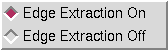
By default, every time an unstructured surface mesh is displayed, the free boundary edges of the surface are extracted to support the edges only display mode. For invalid surface meshes, the edge extraction operation can fail and cause the surface to not be displayed. This menu allows the edge extraction to be turned off during the display of future unstructured surfaces. If edge extraction is turned off, the edges only display will not be shown for unstructured surfaces. Releasing the left mouse button over the desired mode will cause that radiobutton to be set, and future unstructured objects will be drawn in that mode.
Selection of the "Wire Frame Sequencing" submenu causes the following pulldown menu to be displayed.
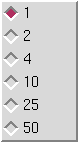
This menu allows the display of unstructured surface meshes to be sequenced by display a subset of the faces. The choices are to display every 1, 2, 4, 10, 25, or 50 faces. Note that this option only works for unstructured surface meshes. An example of the wire frame sequencing mode is illustrated in the following example.
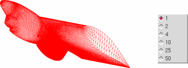
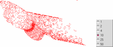
Releasing the left mouse button over the desired sequencing level will cause that radiobutton to be set, and future unstructured objects will be drawn in that mode. This mode can be useful to speed up the graphic display for objects containing a large number of faces. A typical use would be to set the wire-frame sequencing to a large number while the display is being manipulated (rotated, zoomed etc) and then set the wire-frame sequencing back to one once the final display view is set.
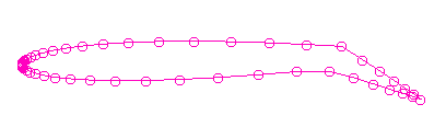
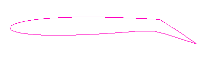
Selection of the "Points on Curves" submenu causes the following pulldown menu to be displayed.
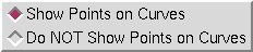
By default, objects consisting of a single curve in MADCAP are displayed with dots at the defined node points on the curve to assist the user in identifying them. This is usually the desired display mode when working in the program. However, there are times when it is desirable to have the dots not be displayed. These radiobuttons are used to control the display mode for individual curve objects. The images below show a typical curve displayed with and without points displayed.
The associated text command is:
view curvepoints {on | off}
Selection of the "Highlight Object Origins" submenu causes the following pulldown menu to be displayed.
All objects in MADCAP are defined as point definition objects, with a definite point ordering scheme. Certain operations require the user to have knowledge of this ordering. For surfaces, the two families of grid lines are referred to as constant N lines and M lines. On constant N lines, the M index varies from 1 to the number of points on the N lines, and vice versa for constant M lines. To assist the user in identifying which lines are which, objects can be drawn with the first segment of the first N and M lines highlighted. The images below show a typical surface displayed with and without the surface origin highlighted.
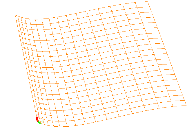
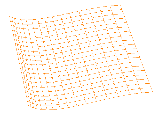
Releasing the left mouse button over the desired option will cause that radiobutton to be set, and the screen will be redrawn such that all currently displayed curves and surfaces are drawn with the object origin highlighted. When highlighted, the constant M = 1 line, on which N varies, is drawn with the first segment highlighted in green and a character "N" drawn at the N = 2 point to show that N varies in this direction. The constant N = 1 line, on which M varies, is drawn with the first segment highlighted in red and a character "M" drawn at the M = 2 point to show that M varies in this direction.
The associated text command is:
view highlight {on | off}
Selection of the "Blanking Mode" submenu causes the following pulldown menu to be displayed.
The setting of the "Blanking Mode" determines how the graphics driver interprets the existence of IBLANK data in the grid dataset. By default, "Blanking On - Show Grid" is set, so that points flagged as holes are not displayed. The user also has the option of drawing with only hole points drawn using the "Blanking On - Show Hole" option, or drawing all points using the "Blanking Off" option.
Releasing the left mouse button over the desired Blanking Mode will cause that radiobutton to be set, and the screen will be redrawn such that all currently displayed surfaces reflect their IBLANK values.
The associated text command is:
view blanking {off | grid | hole}
Selection of the "Color" submenu causes the following pulldown menu to be displayed.
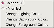
The MADCAP user has great flexibility in the choice of colors to be used for the foreground, background, or lighting models. The two radiobuttons at the top of the pulldown menu are used to cause the main graphics screen to be drawn either in full color on the current background color (Color on BG), or in the current foreground color on the current background color (FG on BG).
In full color mode, specific areas of the screen and the individual objects drawn are assigned colors by the program. To achieve a bi-color display such as black on white, the radiobutton should be set to "FG on BG", and the appropriate colors set using the "Change Background Color ..." and "Change Foreground Color ..." submenus at the bottom of this pulldown menu. Selecting either of these submenus causes the following window to be displayed.
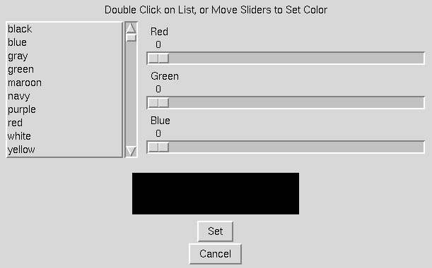
In this window, the full list of X-graphics defined colors available on your system is shown in a scrollable list at the top left. To select a color from this list for either the foreground or background the user must double-click on the color name. This will cause the sliders to move to the corresponding Red, Green, and Blue (RGB) values making up that color. Alternatively, the user may use the sliders to modify the RGB values individually. The rectangle below the sliders reflects the currently set color. When the desired color has been found, select the "OK" button and the background or foreground color will be modified. Choose the "Cancel" button to escape with no action being taken. Using this window for both the foreground and background color, the user can achieve any bi-color display desired, such as red on yellow, orange on blue, or even DarkGoldenrod on PaleTurquoise.
The Color menu is also used to set the color to be used for solid bodies when the Global Display Mode or New Object Display Mode is set to "Lighted". When the "Change Lighting Color ..." option is chosen, the following window is displayed.
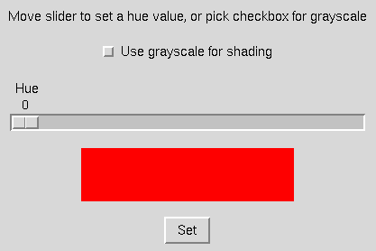
This window provides a checkbox to be used when the user desires a gray-scale for the lighting, as well as a slider to set a hue between 0 and 360. The hue value corresponds to a value on the color wheel, with both 0 and 360 corresponding to red. On this color wheel, yellow has a value of 60, green 120, cyan 180, blue 240, and magenta 300. Moving the slider causes the rectangle to be drawn in the color corresponding to the value set. If the grayscale checkbox is highlighted, the value on the Hue slider is not used.
The associated text commands are:
   view color {coloronbg | fgonbg}
   view fgcolor red green blue
   view bgcolor red green blue
   view lightcolor hue
where red, green, and blue are values between
0. and 1., and hue is a value between 0. and 360., or −1 for
grayscale.
Selection of the "Light Settings" submenu causes the following pulldown menu to be displayed.
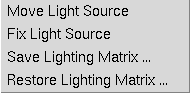
This menu is used to manipulate the light source location used when the Global Display Mode or New Object Display Mode is set to "Lighted". When the "Move Light Source" option is selected, the dials, spaceball, and graphics window rotation and translation buttons cause the light source to move, rather than causing the geometry to move. The light source moves with the same types of body or screen-based transformations that the geometry uses. The geometry image is updated to reflect the new lighting in real time as the light source is moved. When large amounts of graphics data are displayed, this can be a slow process. It is recommended that the light source be set with the minimal amount of data displayed that is required to achieve the desired lighting.
To fix the light source at a particular location, and return the dials to manipulating the geometry, the "Fix Light Source" menu option should be chosen. A window will appear informing the user that the dial function has been set back to geometry manipulation.
Lighting matrices may be saved to file and restored from file with the last two menu options. Selecting either of these causes the following window to be displayed.
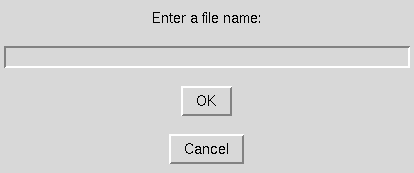
Entering a file name and choosing the "OK" button causes the current lighting matrix to be written to the specified file in "Save" mode, or read and loaded to the program as the current lighting matrix in "Restore" mode.
Lighting matrices may be manipulated at any time, regardless of whether the Global Display Mode and New Object Display Mode are set to "Lighted". Of course, no affect is seen graphically unless Lighted mode is set.
The associated text command is:
view lightsource {move | fix | save filename | restore filename}
Selection of the "Sweep Plane Settings" submenu causes the following pulldown menu to be displayed.
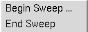
This menu is used to access the automatic grid plane sweeping of structured zonal grids capability in MADCAP. Grid planes in the current display file can be made to automatically sweep, alternately turning on and off the planes requested. Selecting the "Begin Sweep ..." option causes the following window to be displayed.
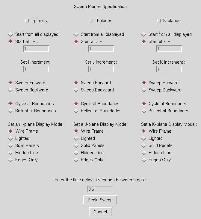
Sweeps are performed on any combination of I, J, or K planes simultaneously, as indicated by the checkboxes set across the top of the window. For any type of plane, there are a number of additional options which may be set. First, a radiobutton must be set indicating whether the sweeps should originate from all displayed planes of the given type, or only from a specfic plane whose index is entered in the entry box. Next, the step increment for the sweep must be entered, and is defaulted to 1. For each plane type, the user may specify that the sweep progress forward or backward. Also the behavior at the 1 and max boundaries is specified with the "Cycle" or "Reflect" radiobuttons. "Cycle" will cause plane 1 to follow plane "max" in the sweep, while "Reflect" will cause plane "max − 1" to follow plane "max". A different display mode can be set for the planes in each direction, and is independent of the currently set Global Display Mode or New Object Display Mode. Finally, a time delay between steps must be entered. It may be impossible to achieve very short time delays, depending on the amount of real time it takes to update the display on each step. If the specified elapsed time has not passed after the screen is updated, the program waits until it has passed. If the screen update has taken longer than the specified time, the program continues with the next update immediately.
When the desired sweep data has been entered, selecting the "OK" button will cause the sweep to begin. To exit the window with no action being taken, select the "Cancel" button.
To stop the grid plane cycling, select the "End Sweep" option under the main GUI Sweep Planes menu. It may take an additional step before the cycling stops. Any grid planes displayed as a result of the cycling action remain displayed after the "End Sweep" has been selected.
The associated text command is:
   view sweep time {ijk | ij | jk | ik | i | j | k} \
       {all | start_index} increment {for | back} \
       {cycle | reflect} {wireframe | edges | solid | hidden | lighted} \
      [{all | start_index} increment {for | back} \
       {cycle | reflect} {wireframe | edges | solid | hidden | lighted}] \
      [{all | start_index} increment {for | back} \
       {cycle | reflect} {wireframe | edges | solid | hidden | lighted}]
Selection of the "Axis Orientation on Reset ..." submenu causes the following window to be displayed.
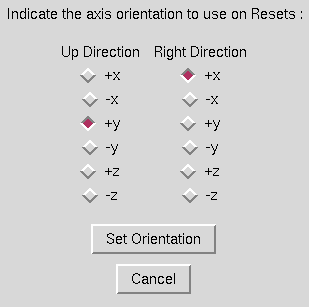
MADCAP users have the option of defining the viewpoint to be used as the default axis orientation. This axis orientation is used whenever the user chooses to reset the view, and is also the basis for any transformations resulting from setting view angles. Thus, if the user prefers to always have a reset present a view from the front, with the up direction in the screen up direction, this can be set regardless of the coordinate system of the geometry by ensuring that the correct Up Direction and Right Direction are set in this window.
The default orientation is set by choosing a radiobutton from each column, Up Direction and Right Direction. The same axis cannot be set for both directions. The orientation of the third axis, into the screen or out of the screen, will be determined such that the right hand rule is followed. After the correct radiobuttons have been set, the "OK" button should be picked to set the default. This selection does not perform a reset, but only establishes a default orientation.
To escape from this window with no action being taken, select the "Cancel" button.
The associated text command is:
   view axisorient {+x | -x | +y | -y | +z | -z} {+x | -x | +y | -y | \
      +z | -z}
where the first direction specifies the up direction and the second
specifies the right direction.
Selecting the "Surface File Sort Mode" submenu causes the following pulldown menu to be displayed.
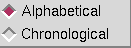
The geometry created in the surface geometry module of MADCAP is stored by an assigned name in the surface geometry file. At times it is desirable to access these names in the graphics window name list either alphabetically or chronologically. The "Surface File Sort Mode" option is used to determine how the surface names are presented to the user. In "Alphabetical" mode, newly assigned names are merged into an alphabetical presentation of the surface name list. In "Chronological" mode, newly assigned names are always appended to the bottom of the list. This mode also provides the user with a sense of how recently the surfaces have been created. The mode can be switched as desired at any time.
The associated text command is:
view sortmode {alpha | chron}
Selection of the "Axis Mode" submenu causes the following pulldown menu to be displayed.
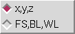
Choosing between the two radiobuttons switches the graphics display between plotting the pure x, y, z coordinate data existing in the open files to plotting the data in a fuselage station (FS), buttline (BL), waterline (WL) coordinate system. Relationships between x,y,z and FS,BL,WL coordinates are established under the File Set FS, BL, WL Directions menu option for each open file in the system.
When the mouse is released over the requested coordinate system, the graphics are updated to reflect the selected option. In this manner, two files containing the same geometry but in different coordinate systems (for instance, y-up and z-up) can be viewed consistently.
The associated text command is:
view axismode {xyz | fsblwl}
Some MADCAP operations raise the text window and scroll information to it. The user controls how many lines are output before being prompted to continue or end with this view command. The window shown below is presented after selecting the command from the View menu.
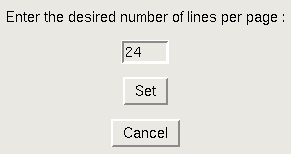
Simply enter the number of lines per page desired, and hit the OK button. This will set the lines per page for any scrolling output function desired in MADCAP. To escape with no action being taken, pick the Cancel button.
The associated text command is:
view lines_per_page nlines
Last updated 18 July 2007