
Selection of the Modular Aerodynamic Design Computational Analysis Process (MADCAP) "Overlapping" menu item produces the drop down menu shown below.
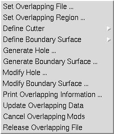
There are currently twelve selections under the Overlapping menu. They are:
Help on these submenus is available below.
Selection of the "Set Overlapping File ..." submenu causes the following window to be displayed.
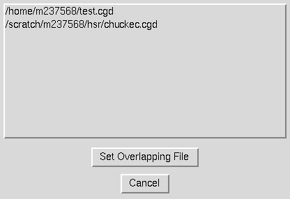
The current list of .cgd files that have been opened in MADCAP is displayed in the list box in this window. (See File Open help for details on opening files in MADCAP.) Since overlapping hole and fringe data (IBLANK data) is stored only in the .cgd file, other file types currently open in MADCAP are not displayed in this list.
Selecting a file name from this list will cause it to be highlighted. When the desired file has been selected, pick the "Set Overlapping File" button at the bottom of the window. The window will be shut down and a message will appear in the MADCAP message box indicating that the file has been set as the Overlapping file. Only one file can be set as the Overlapping File at any given time.
To escape from this window with no action being taken, select the "Cancel" button.
The associated text command is:
ol file name filename
Selection of the "Set Overlapping Region ..." submenu causes the following window to be displayed.
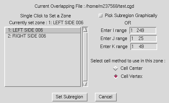
This window is used to set the zone and subregion of that zone in which the overlapping operations are to be applied. A zone and subregion must be set before most of the overlapping operations can be performed. The scrollable list on the left of the window contains the list of zones in the currently set overlapping file. A single click on a zone name in this list will change the currently set zone to the selected zone. The name of the currently set zone is displayed at the top of this list, and is defaulted to the first zone in the list the first time the window is displayed.
Immediately to the right of the scrollbar are a set of entry boxes in which to enter I, J, and K subranges. By default, the ranges reflect the complete zone. The user can modify these ranges to any subregion of the full zone that is desired. If the user would prefer to select the corners of the subregion graphically instead, the checkbutton marked "Pick Subregion Graphically" should be highlighted. This will disable entries in the boxes, and the user will be prompted to pick the corners of the subarea from the graphics screen after exiting the window.
Finally, two radiobuttons are provided in which the user should indicate whether the zones specified are to be operated on using a cell- centered or cell-vertex method.
After ensuring that the correct zone and region have been set, select the "Set Subregion" button at the bottom of the screen. This will cause the window to close, and a message will appear in the graphics region indicating that the desired area has been set. If the subregion was specified to be picked graphically, the program will prompt the user to pick the corners for the subregion, using the left mouse button to pick points from the displayed surfaces.
If the user attempts to change the overlapping region or file after changes have been made but before selecting the "Update Overlapping Data" submenu, the following window is presented.
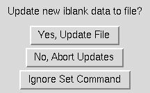
Selecting the "Yes, Update File" button has the same effect as selecting the "Update Overlapping Data" submenu. Selecting the "No, Abort Updates" button has the same effect as selecting the "Cancel Overlapping Mods" submenu. Selecting the "Ignore Set Command" button ignores the attempt to change the region or file, with no changes being made to the current settings.
To escape from the Set Overlapping Region window with no action being taken, select the "Cancel" button.
Exiting this window causes the following text commands to be issued.
   ol zone zone number
   ol set {cell center | cell vertex}
   ol subregion {I range J range K range | all}
Selection of the "Define Cutter" submenu causes the following cascade menu to be displayed.
Three types of cutters may be used to cut holes in the selected zone and subregion. Each type requires its own unique inputs. Selecting one of the types from the cascade menu will cause a window to be displayed for entering these inputs. The three types of cutters are:
Selecting the "Surface ..." submenu item causes the following window to be displayed.
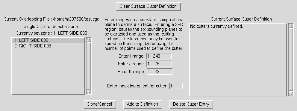
A surface cutter is used to define a cutting surface by computational planes in any zone. In the classic example of a wing zone overlapped on a background grid, the user may want to set a cutting surface at the J = 21 plane of the wing grid and cut away all points in the background zone falling inside this surface. To define a surface cutter in this window, the user first selects a zone from the list of zones in the box at the left of the window. This causes the full zone ranges to appear in the I, J, and K range entry boxes at the middle of the window.
To define a range of points on a computational surface of the zone, the user should modify the entry boxes to identify a constant I, J, or K plane and a subregion of the other two directions. If a three-dimensional region is entered, the cutting surface will be defined by the set of six bounding planes making up the region.
The entry box for an "index increment" can be used to speed up the hole generation operation. The default value is 1, meaning that every point in the computational range entered is used to define the cutting surface. By entering larger integer values, a coarser definition of the cutting surface can be described which may speed up the hole generation.
After defining the correct surface cutter, the user should select the "Add to Definition" Button at the bottom of the window. This will cause the defined surface cutter to be added to the current surface cutter definition. The current definition is shown in the box to the right of the window. After the definition has been added, the window is redrawn with the entered data added to the "Current Surface Cutter Definition" box. If no further surface cutters need to be defined, the "Done/Cancel" button should be selected. If the user wants to delete one of the components in the current definition, the "Delete Cutter Entry" button should be selected, and the following window will be displayed.
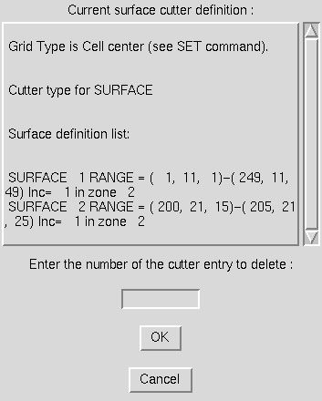
The box at the top is the same cutter definition as in the previous window, but the user now has an entry box in which to enter the numeric identifier for the component of the surface cutter to be deleted. Enter the number in the entry box and hit the "OK" button to cause the specified part of the surface cutter to be deleted.
To completely clear out the current surface cutter definition, the "Clear Surface Cutter Definition" button at the top of the main definition window should be selected.
Note that this window is used only to define a cutter, and does not cause any holes to be cut itself. After all cutters that are desired have been defined, the "Generate Hole" menu should be used to actually proceed with hole cutting.
Use of this window causes a form of the following command to be issued.
   ol cutter surface [new | {range | region} [in] zone zonnum range \
      [increment n]]
If the Delete Cutter window is used, the following command is issued.
ol modify cutter delete entrynumIf the Clear Cutter button is used, the following command is issued.
ol cutter surface clear
Selecting the "Index ..." submenu item causes the following window to be displayed.
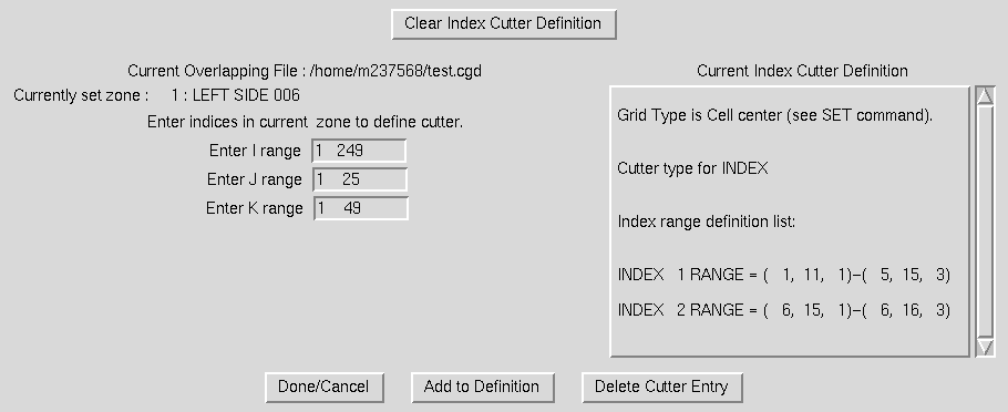
An index cutter is used to define a set of points in the current zone that should be marked as hole points. All points falling within the specified range will be marked to be set as hole points when the "Generate Hole" command is issued. The full zone dimensions are initially entered in the I, J, and K range entry boxes in this window. To set a different range of points, the user simply enters the desired values in the entry boxes.
After setting the correct range of points, the user should select the "Add to Definition" Button at the bottom of the window. This will cause the defined zone range to be added to the current index cutter definition. The current definition is shown in the box to the right of the window. After the definition has been added, the window is redrawn with the entered data added to the "Current Index Cutter Definition" box. If no further index ranges need to be specified, the "Done/Cancel" button should be selected. If the user wants to delete one of the components in the current definition, the "Delete Cutter Entry" button should be selected, and the following window will be displayed.
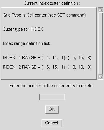
The box at the top is the same cutter definition as in the previous window, but the user now has an entry box in which to enter the numeric identifier for the component of the index cutter to be deleted. Enter the number in the entry box and hit the "OK" button to cause the specified part of the index cutter to be deleted.
To completely clear out the current index cutter definition, the "Clear Index Cutter Definition" button at the top of the main definition window should be selected.
Note that this window is used only to define hole regions, and does not actually change the points in the file. After all ranges that are desired have been defined, the "Generate Hole" menu should be used to actually proceed with setting the points to hole points in the file.
Use of this window causes a form of the following command to be issued.
ol cutter index [range] rangeIf the Delete Cutter window is used, the following command is issued.
ol modify cutter delete entrynumIf the Clear Cutter button is used, the following command is issued.
ol cutter index clear
Selecting the "Punch ..." submenu item causes the following window to be displayed.
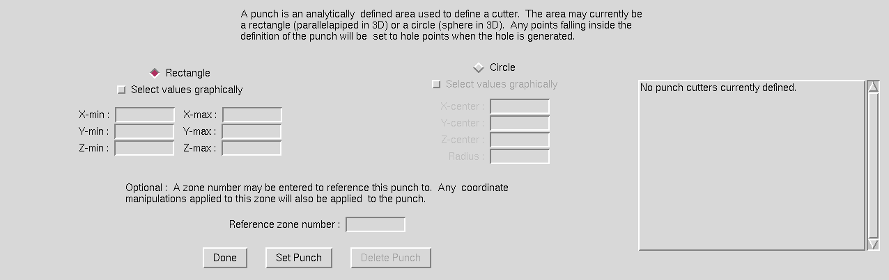
A punch is an analytically defined surface which can be used to indentify points to be set to hole points, similar to a paper hole punch being used to create a circular hole in a sheet of paper. Two types of punches can currently be defined in MADCAP - a rectangular box or a sphere. Two radiobuttons are provided to set the type of punch to be defined, with the rectangular punch the initial default. For a rectangular punch, the user enters the x, y, and z coordinates of two opposite corners of the rectangular region in the entry boxes. The entry boxes for the circular punch are disabled when the Rectangle radiobutton is selected. When the Circle radiobutton is selected, the entry boxes for the x, y, and z coordinates of the center of the sphere and the radius of the sphere are enabled, and the Rectangle entry boxes are disabled. For both the rectangle min/max and the sphere center/radius, the user has the option of highlighting the "Select values graphically" checkbutton. In this case, the entry boxes may remain empty, and the program prompts the user to identify these values via screen picks from the displayed surfaces.
For some multidisciplinary applications where overlapping grids are automatically moved, like store separation, it may be desirable to use a punch to cut the initial hole. As the store moves and rotates against the fixed background grid, it is necessary that the punch used to define the hole move and rotate with the grid. For this purpose, an optional Reference zone number may be entered in the bottom entry box. This "anchors" the punch to a specific zone in the file, such that the punch definition is updated along with any motion of the specified zone.
After the punch has been defined, the user should select the "OK" button to set the punch definition. To escape without defining a punch, select the "Cancel" button. Note that unlike the surface cutter and index cutter only one punch definition can be defined at a time. Specifying a new punch definition will replace the current punch cutter definition. If more than one punch needs to be defined, the user should define a punch, generate its hole using the Generate Hole command, and then define the next punch.
Use of this window causes a form of the following command to be issued.
ol cutter punch [{rectangle | circle} coord_data [REF_ZONE zonnum]]
where coord_data has the form:
   min xval yval zval max xval yval zval (For a rectangular punch)
   center xval yval zval radius val (For a circular punch)
Selection of the "Define Boundary Surface" submenu causes the following cascade menu to be displayed.
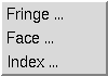
Three types of boundary surfaces may be defined in the selected zone and subregion. Each type requires its own unique inputs. Selecting one of the types from the cascade menu will cause a window to be displayed for entering these inputs. The three types of boundary surfaces are:
Selecting the "Fringe ..." submenu item causes the following window to be displayed.
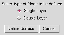
A fringe boundary surface is used to mark the points surrounding a hole as a boundary on which a boundary condition can be set (a "fringe"). The only input required for setting this type of boundary surface is to specify whether a single layer or double layer of points surrounding a hole are to be marked as fringe points. Two radiobuttons are provided for this purpose. After selecting the desired option, the user should select the "Define Surface" button to set a boundary fringe definition. To escape with no action being taken, select the "Cancel" button.
Note that this operation does not actually set the fringe points, but only the mode to use when the Generate Surface command is used.
Using this window causes the following commands to be issued.
   ol srfacer [mode] {single | double}
   ol srfacer [mode] fringe
Selecting the "Face ..." submenu item causes the following window to be displayed.
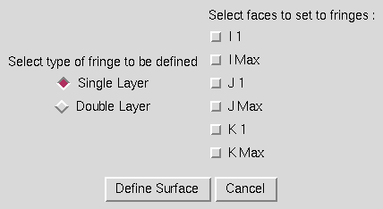
This mode is used when all of the points on one of the six computational faces of a zone are desired to be set to fringe points. As with the basic fringe boundary surface around a hole, a full face fringe boundary surface may be generated as a single layer or double layer of points. The user selects the appropriate radiobutton for this option at the left of the window, and then uses the checkbuttons to the right of the window to identify any set of faces to be marked as fringe boundaries. After setting the desired options, the "Define Surface" button should be selected. To escape with no action being taken, the "Cancel" button is selected.
Note that this operation does not actually set the fringe points, but only the mode to use when the Generate Surface command is used.
Using this window causes the following commands to be issued.
   ol srfacer [mode] {single | double}
   ol srfacer [mode] face [[on | off] [i1] [imax] [j1] [jmax] [k1] [kmax] ...]
Selecting the "Index ..." submenu item causes the following window to be displayed.
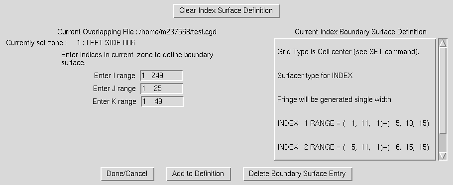
The index boundary surface is used to specify a set of points in the current zone which are to be defined as a boundary surface on which a boundary condition can be set. All points within the ranges of points specified will be able to be assigned a boundary surface id which can then have a boundary condition specified. The entry boxes for I, J, and K ranges to the left of the window are initially set to the full zone. The user can modify these entry boxes to set the desired region of the zone. After setting a range, the "Add to Definition" box should be selected to add the specified range to the current index boundary surface definition. The window will then be redrawn with the specified ranges added to the current definition seen in the box to the right of the window. If the user wants to delete a certain entry from the current boundary surface definition, the "Delete Boundary Surface Entry" button should be used and the following window will be displayed.
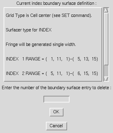
The box at the top is the same surface definition as in the previous window, but the user now has an entry box in which to enter the numeric identifier for the component of the index surface to be deleted. Enter the number in the entry box and hit the "OK" button to cause the specified part of the index boundary surface to be deleted.
To completely clear out the current index surface definition, the "Clear Index Surface Definition" button at the top of the main definition window should be selected.
Note that this window is used only to define points to be set as boundaries, and does not actually change the points in the file . After all ranges that are desired have been defined, the "Generate Boundary Surface" option should be used to actually proceed with setting the points to boundary points in the file.
Use of this window causes a form of the following command to be issued.
ol srfacer [mode] index [range] rangeIf the Delete Surface Entry window is used, the following command is issued.
ol modify srfacer delete entrynumIf the Clear Index Surface button is used, the following command is issued.
ol srfacer [mode] index clear
Selection of the "Generate Hole" submenu causes the following window to be displayed.
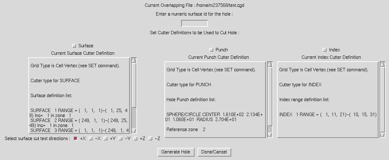
This window is composed primarily of scrollable text boxes containing the currently set definitions of the three types of cutters - surfaces, punches, and index ranges. At the top of the window is an entry box in which the user should set a numeric surface id to be used to label the hole generated by this command. After setting the id, the user should select any or all of the checkbuttons at the top of the text boxes to indicate which cutter definitions should be used to generate holes with the input surface id. Additionally, for surface cutter definitions, the user should specify which directions to use for the test to determine if a point falls inside or outside the defined surface cutter. Checkbuttons are provided at the bottom of this textbox for this purpose.
Holes of different types may be specified to be cut at the same time with this command, but all will have the same numeric id after they have been generated. When the desired data has been entered, the "Generate Hole" button should be selected and MADCAP will proceed to cut the holes. Informational messages are output to the message box, and the graphic display is updated to reflect the new surface iblank data (depending on the setting of the blanking mode in the main viewing menu). To escape this window with no action being taken, select the "Done/Cancel" button.
Use of this window may cause any of the following commands to be issued.
   ol surface [surface_name | all]
   ol set cut test directions [[[on | off] {+/-x | +/-y | +/-z | all } ] ...]
   ol cutter {surface | punch | index}
   ol generate hole
Selection of the "Generate Boundary Surface" submenu causes the following window to be displayed.
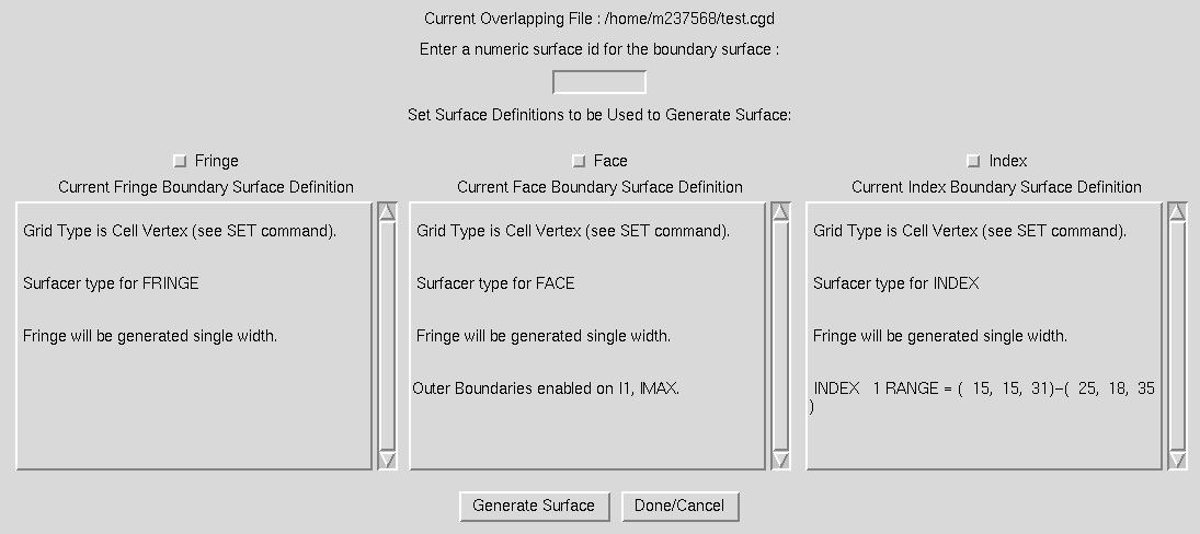
This window is composed primarily of scrollable text boxes containing the currently set definitions of the three types of boundary surfaces - hole fringes, zone faces, and index ranges. Checkbuttons at the top of these boxes are used to set the types of boundary surfaces to be generated with this command. At the very top of the window is an entry box in which the user should set a numeric surface id to be used to label the fringe to be generated. If the "fringe" boundary surface type is selected, the fringe will be generated around the hole with the same label as the one entered. For the other types, the entered surface id will be used for the new fringe generated.
When the correct data has been entered, the "Generate Surface" button should be selected. To exit with no action being taken, select the "Done/Cancel" button.
Use of this menu will cause the following commands to be issued.
   ol surface [surface_name | all]
   ol srfacer {face | fringe | index}
   ol generate surface
Selection of the "Modify Hole" submenu causes the following window to be displayed.
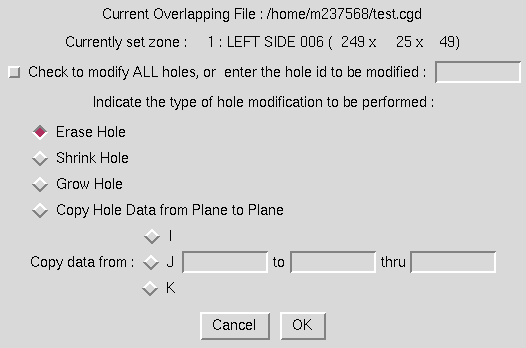
Hole modification can be performed on either all existing holes in the defined subregion, or on a specific hole. To modify all holes, set the checkbutton at the top of the window. Otherwise, enter the id for the hole to be modified in the entry box. Four types of hole modification can be performed. First, holes can be erased completely. Note that this also erases any associated fringes that may have been generated around the hole. A hole can also be shrunk or grown using the next two radiobuttons. In these cases, an extra layer of points are either removed or added to the hole. Finally, with the "Copy" radiobutton, the hole points with the specified id that are currently set on a given I, J, or K plane can be copied to a different plane or range of planes. If the "copy" radiobutton is selected, one of the I, J, or K radiobuttons, and the entry boxes for the plane to copy from and the plane range to copy to must be filled in.
After the correct options have been set, the user should select the "OK" button. To escape with no action being taken, the "Cancel" button should be selected. To save the modifications to file, the update main menu option must still be selected.
Use of this menu will cause the following commands to be issued.
   ol surface [surface_name | all]
   ol modify hole {erase | shrink | grow | copy {i | j | k m to n1 [thru n2]}}
Selection of the "Modify Boundary Surface" submenu causes the following window to be displayed.
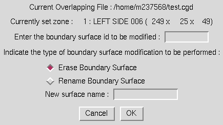
Boundary surface modification can take two forms - either erasing the stored definition of a boundary surface, or renaming a boundary surface. In either case, the surface id to be modified must be entered in the entry box at the top of the window, and the appropriate radiobutton should be selected. If the "Rename" option is selected, the new name should be entered in the box provided.
After the correct options have been set, the user should select the "OK" button. To escape with no action being taken, the "Cancel" button should be selected. To save the modifications to file, the update main menu option must still be selected.
Use of this menu will cause the following commands to be issued.
   ol surface [surface_name | all]
   ol modify surface {erase | rename from old_name to new_name}
Selection of the "Print Overlapping Information" submenu causes the following window to be displayed.
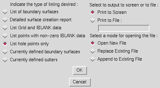
This window is used to set the type of overlapping information to be reported on, and where to send the desired output. Seven types of listing can be obtained - a list of the holes and boundary surfaces in the current subregion, a detailed report on how holes and surfaces were created, a listing of the grid (x,y,z) and iblank data in the current region, a listing of only the points with iblank data set, a listing of hole the hole points, the currently defined boundary surfaces, and the currently defined hole cutters. The type of listing obtained is controlled by the radiobuttons on the left. On the right, the user may choose to print the listing either to the screen or to file. If the Print to File radiobutton is selected, the user must enter a file name for the listing and whether to open a new file, overwrite an existing file, or append to an existing file.
The associated text command is:
   ol print {surface list | surface creation report | grid | iblank holes | \
      srfacer mode | cutter mode}
If output is directed to a file, MADCAP precedes the bc print command
with a file open command as follows:
file open list filename [mode { new | replace | append }]
Selection of the "Update Overlapping Data" submenu causes the overlapping data generated in the currently set overlapping region to be written to the currently set overlapping file. Until this action has been taken, the overlapping data is only updated in program memory, and not to the actual .cgd file.
Selection of the "Cancel Overlapping Mods" submenu causes the overlapping data that has been set on the currently set overlapping region to be canceled out, and replaced with the original set of overlapping data from the currently set overlapping file. This action is non-recoverable, as all overlapping information stored for the current region in program memory is restored to the file state existing before the set overlapping data operations were begun. To save the changes to file, use the "Update Overlapping Data" submenu.
Certain regions of program memory are allocated when an overlapping file is first set, and used throughout the overlapping process. This memory remains allocated and usable as long as an overlapping file is set. If the MADCAP user has completed all desired overlapping operations, it may be desirable to use the "Release Overlapping File" submenu to free up the memory associated with setting overlapping data. This is never a required operation, but deallocates resources that may be required elsewhere. After selecting this submenu, no overlapping file will be set, and the user must respecify a file before again using the overlapping menus.
Last updated 19 July 2007