
Selection of the Modular Aerodynamic Design Computational Analysis Process (MADCAP) "Boundary Conditions" menu item produces the drop down menu shown below.
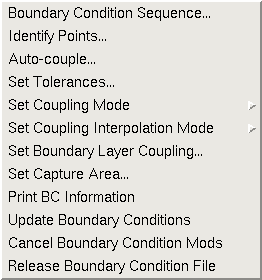
There are currently twelve selections under the Boundary Conditions menu. They are:
Help on these submenus is available below.
Selection of the "Boundary Condition Sequence ..." submenu causes the following window to be displayed.
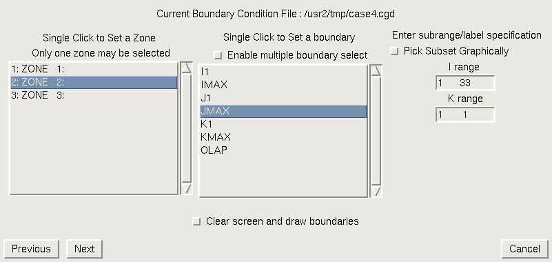
This window is used to set the zone, and regions of that zone, at which a unique boundary condition is to be set. The scrollable list on the left of the window contains the list of zones in the current working file. A single click on a zone name in this list will change the currently set zone to the selected zone, and display a list of boundaries in that zone in the box to the right.
When a single boundary from the boundary list is selected, the applicable index ranges are displayed to the right. These allow the user to select index subranges in the case of a structured mesh, or a point range for unstructured surfaces, at which the boundary condition should be applied. The subrange of the selected computational boundaries is, by default, the entire boundary. If a smaller subregion of a boundary is desired, the limits may be entered in the entry boxes provided. Alternatively, the user may turn on the "Pick Subset Graphically" checkbox, and the user will be prompted to pick the corners of the subarea from the graphics screen after exiting the window.
Multiple boundaries may be selected simultaneously by first picking the radio button labeled "Enable multiple boundary select" at the top of the boundary list, then selecting the desired boundaries while holding down the Control key. This allows the same boundary condition to be quickly set on more than one boundary. Note that this only applies when a boundary condition is being set for the entire boundary; index subranges cannot be set when multiple boundaries are selected.
If the checkbox at the bottom of the screen is enabled, MADCAP will clear the screen and redraw only the boundaries that have been set in this window. This is often desirable, especially if you are setting the subset graphically, since it will cause the selected face to be redrawn and rescaled at the center of the screen where it is easy to pick from.
After ensuring that the correct zone and regions have been set, select the "Next" button at the bottom of the screen to close the current window and open the "Assign/Change Boundary Condition" window.
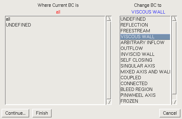
To the left of this window is a list of all boundary conditions currently set for the specified zone and region, as well as the special keyword "all". The user may change the boundary conditions of all points in the region by choosing the "all" keyword from the list, or change boundary conditions selectively by choosing any of the existing boundary condition types to affect only points with that boundary condition. The list box on the right contains the full list of boundary conditions that are available.
When the desired change types and new boundary conditions have been chosen, selecting "Finish" at the bottom of the window will close the window. Note that at this point the boundary conditions are updated in program memory only, not in the .cgd file itself. To actually update the boundary conditions in the .cgd file, select Update Boundary Conditions from the main Boundary Conditions menu. You can also select Cancel Boundary Condition Mods to delete the boundary condition update, leaving the boundary conditions in the .cgd file unchanged.
If additional boundary conditions are to be set, instead of selecting "Finish" at the bottom of the "Assign/Change Boundary Condition" window, you can select "Continue" to go back to the "Set Boundary Condition Zone and Boundary" window. Then select the desired zone for the additional boundary conditions.
At this point, since the boundary conditions that were chosen for the previously-selected zone and region haven't yet been updated in the .cgd file, the following confirmation subwindow will pop up.
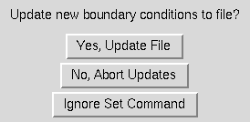
Selecting the "Yes, Update File" button has the same effect as selecting "Update Boundary Conditions" from the main Boundary Conditions menu. Selecting the "No, Abort Updates" button has the same effect as selecting "Cancel Boundary Condition Mods" from the main Boundary Conditions menu. Selecting the "Ignore Set Command" button ignores the attempt to set a new zone for additional boundary conditions.
After finishing with the confirmation subwindow, you can continue the procedure described above to set additional boundary conditions.
Several of the possible boundary condition specfications cause additional input windows to be displayed. If the "Coupled" boundary condition is specified in the "Assign/Change Boundary Condition" window, the following window is displayed.
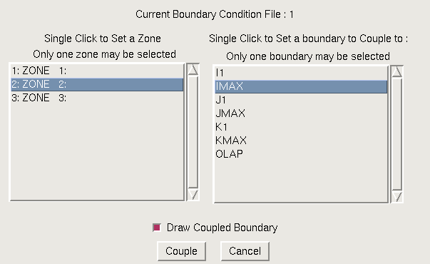
This window is used to set the zone and boundary that the currently-specified boundary condition region is to be coupled to. If the current region consists of zone faces, the OLAP boundary must not be chosen as the boundary to couple to, or an error will be generated. The OLAP boundary can only be used when the subregion consists of overlapping labels. The zone face buttons can be used for any type of coupling. The list box on the left shows the list of zones in the current boundary condition file. Selecting a zone from the list on the left, and then a computational face (or OLAP) from the list on the right, will set them as the zone and boundary to which the currently-specified boundary condition region will be coupled.
The checkbutton at the bottom of the window is used to force MADCAP to draw the selected coupling boundary before actually proceeding with the coupling. This may be useful to help visualize whether the correct set of points has been coupled.
When the correct zone and boundary have been set, the "Couple" button is selected to proceed with the zone coupling. To escape from this window with no action being taken, select the "Cancel" button.
If the "Connected" boundary condition is specified in the "Assign/Change Boundary Condition" window, the following window is displayed.
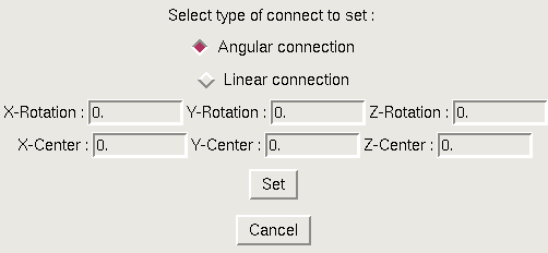
This window is used to set both the type of connection to be performed, as well as the required information for that type of connection. At the top of the window are two radiobuttons, used to specify whether an angular or linear type of connection is to be performed. The window is displayed above as it appears for angular connection, in which case the window also displays six entry boxes in which to set a center of rotation for the angular connection, and the amount of rotation about each axis to be performed to accomplish the connection. If the radiobutton is switched to the linear connection type, the window is modified as shown below.
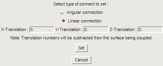
In this case, only three entry boxes are available, in which to specify the amount of x, y, and z translation to perform to do the connection. In either case, the same window described above for zone coupling is presented with the word "Couple" replaced by the word "Connect". As with coupling, the user specifies a zone and boundary to connect to utilizing the connect data specified on the previous window.
If the "Bleed Region" boundary condition is specified in the "Assign/Change Boundary Condition" window, the following window is displayed.
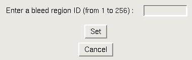
Up to 256 different bleed regions may be set in a given .cgd file. This window is used to simply enter an ID number for the Bleed Region that is being set on the currently-specified boundary condition region. Selecting the "Set" button will cause the defined region's boundary condition to be changed to the bleed region ID entered here. Selecting the "Cancel" button ends the operation with no action being taken.
Selection of the "Identify Points ..." submenu initially causes a MADCAP prompt to be displayed asking the user to select from the graphics screen a surface on which to graphically identify the points' currently set boundary conditions. After responding to this select prompt, the following window is displayed to the user.
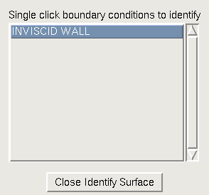
The list box contains the list of all boundary conditions existing on the selected surface. Single clicking on one of these boundary conditions will graphically identify the points on the selected surface, using markers in the graphics display, that correspond to that boundary condition. The Identify Points window will remain open, allowing points corresponding to other boundary conditions on the selected surface to be identified. When the "Close Identify Surface" button is selected, the window is closed and all identifying markers are erased from the display. A typical grid surface with identifying markers displayed is shown below.
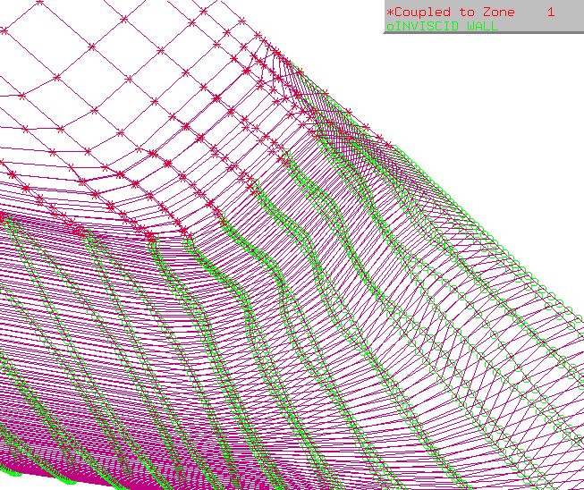
Each boundary condition to be identified is given a unique color/marker combination from a set of three markers (*,o,x) and six colors (red, green, blue, cyan, magenta, yellow), resulting in 18 different possible unique markers before duplication. On the above figure, points tagged as inviscid wall are displayed as green circles while points coupled to zone 1 are displayed with red asterisks. A legend is provided in the upper right corner. Boundary condition identification markers are turned off while the image rotates or is being centered, but are turned back on when the operation is completed. This results in faster image manipulation when markers are displayed.
Selection of the "Auto-couple ..." submenu causes the following window to be displayed.
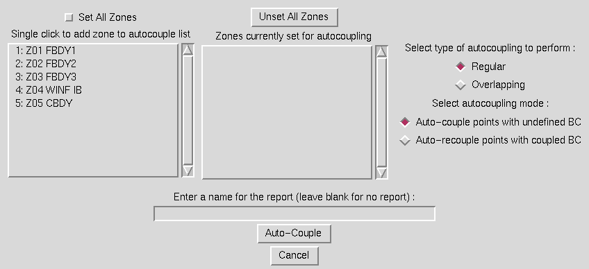
The list box on the left displays the full list of zones existing in the currently set boundary condition file. Any zone selected from this list is added to the list box on the right, which reflects the set of zones being set to perform automatic coupling in. Buttons are provided at the top of the window to either set all zones or clear the auto-coupling list. Both lists are vertically scrollable. The first set of radiobuttons to the right of the list boxes control whether the automatic coupling is performed in regular face-to-face coupling mode or overlapping mode. The second set of radiobuttons controls whether to auto-couple all undefined points, or to only re-couple the selected zones to whatever they were previously coupled to. An entry box is also provided in which a name for the report file generated by the autocoupling module can be entered. Leaving this box blank will cause no report to be generated. Once the set of zones to auto-couple has been set, the "Auto-Couple" button should be selected, and the window will disappear and MADCAP will proceed to autocouple the specified zones. To escape with no action being taken, the "Cancel" button should be selected.
The associated text command is:
   bc automatic [couple | recouple] {mode regular | overlapping} \
      [zone {all | zonelist}] [report filename]
Selection of the "Set Tolerances ..." submenu causes the following window to be displayed.
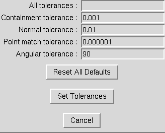
The window consists primarily of five entry boxes in which to enter the desired tolerances to be used during coupling. There are four primary coupling tolerances: containment, normal, point match, and angular. All tolerances can be changed simultaneously by entering a value in the "All tolerances" entry, or individual tolerances can be changed with the separate entry boxes. The values shown above are the current default tolerances, which can be reset at any time by picking on the "Reset All Defaults" button. When the desired tolerances have been entered, the "Set Tolerances" button should be selected, and the new tolerances will be in effect for any future coupling. To escape with no action being taken, the "Cancel" button should be selected.
Containment tolerance controls how far outside the bounds of a cell a point can be and still be coupled to that cell. This is sometimes important along the edges of two non-point-matched boundaries. Normal tolerance controls how far a point must be projected normal to its own surface before finding an intersection with a cell in the face being coupled to. Angular tolerance controls how large the angle between the normals at the grid point being coupled and a candidate point to couple to can be. Point match tolerance is used in conjunction with point match coupling mode, and specifies how far apart points can be and still allow points to be point-match coupled.
The associated text command is:
   bc tolerance {containment | normal | point match | angular | all} \
      {default | tolerance}
Selection of the "Set Coupling Mode" submenu causes the following pull-down menu to be displayed.
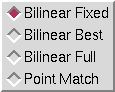
Four different modes can be set for performing coupling: bilinear fixed, bilinear best, bilinear full, and point match. Radiobuttons are provided for each of these modes. In Bilinear Best mode, coupling is attempted at each coupled or from type ( for coupling from type all and undefined are the same ) point on the boundary. If the point matched the from type, or if the point was coupled but the new coupling provides a better trifactors check than the old, the boundary condition is updated to the new coupling. In Bilinear Fixed mode, only from type points are coupled. Bilinear Full mode should be used only when the number of points to be coupled is small, due to the time- consuming nature of this mode. In this mode, a full coupling search is performed in place of the fast search methods normally used. This is rarely required, but may be useful to couple points that for some reason cannot be located using fast search methods. Since this method is time consuming and meant only for small detailed problem areas, it is not available in a "best" mode. Point match coupling is used to force every point to couple to its nearest counterpart in the coupled zone as if they were in fact the same point - that is, coupled exactly to a grid point and not to the interior of a grid cell. This is only useful when grids should in fact be point matched but are not exactly point matched due to small numerical differences.
The associated text command is:
bc couple mode {point match | bilinear | bilinear best | bilinear full}
Selection of the "Set Coupling Interpolation Mode" submenu causes the following pull-down menu to be displayed.
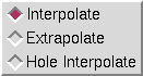
The Coupling Interpolation Mode controls how the coupling interpolation factors are set when a point couples to the exterior of a cell. When the mode is set to Interpolate, the interpolation factors are limited to the range 0. to 1., such that the point will couple to the edge of the target cell. If the mode is set to Extrapolate, the interpolation factors can be set less than 0. or greater than 1., so that during flow solver coupling, data may be extrapolated from the edges of the coupled cell. The Hole Interpolate mode is a special case for overlapping coupling. Normally, if a point is overlap coupled to the interior of a cell, the computed interpolation factors will be used even if some of the points on the cell are flagged as hole points. Setting Hole Interpolate mode will force the interpolation factors to project the coupling to the nearest cell face with no hole points, such that coupling to the interior of a cell containing hole points is prohibited.
The associated text command is:
bc couple mode {interpolate | extrapolate | hole_interpolate}
Selection of the "Set Boundary Layer Coupling" submenu causes the following window to be displayed.
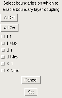
Boundary layer coupling should be used on edges of coupled faces that are walls, especially if the wall edge in the zone being coupled to is not point matched with the wall edge on the boundary being coupled. This ensures that the coupling parameters do not allow boundary layers to couple outside adjacent boundary layers or to be swallowed by adjacent zones by being entirely coupled to the first cell of the adjacent zone. For example, if the surface of a cylinder is described by the J1 surface in both zone 1 and zone 2, but zone 2 has a different set of circumferential points on the cylinder than zone 1, then boundary layer coupling should be enabled on the J1 boundary when coupling zone 1 IMAX to zone 2 I1, and vice versa. The window shown above simply provides checkboxes for each boundary, with buttons provided to turn on or off all boundaries. Boundary layer coupling will be performed on any edges where the checkbutton is set. Select the "OK" button to set the desired boundary layer coupling, or the "Cancel" button to escape with no action being taken.
The associated text command is:
   bc couple mode boundary layer {on | off} {all | i1 | imax | j1 | jmax | \
      k1 | kmax}
Selection of the "Set Capture Area" submenu causes the following window to be displayed.
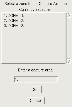
If a mass flow ratio is specified in the Wind-US input file for an outflow boundary condition, the .cgd file must contain a value for the inflow capture area for the associated zone. This window is used to enter a value for this capture area. The user should first select the zone to set the capture area in from the list of zones at the top of the window. Next, a value should be entered for the desired capture area. The value entered should be in the scale and units of the actual geometry being run. Selecting the "OK" button will cause this value to be stored in the specified zone of the currently set boundary condition file. To escape with no action being taken, select the "Cancel" button.
The text commands generated by are:
   bc zone zone number
   bc capture area [is] capture area
Selection of the "Print BC Information" submenu causes the following window to be displayed.
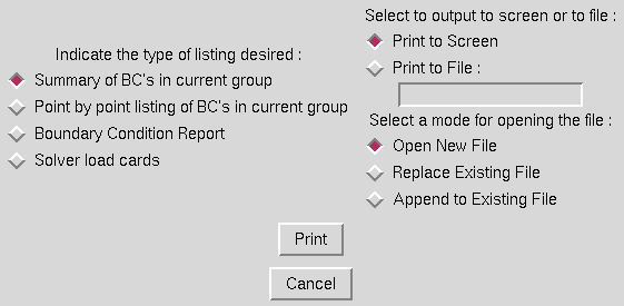
This window is used to set the type of boundary condition information to be reported on, and where to send the desired output. Three types of listing can be obtained - a summary of the boundary conditions in the current group, a point by point listing of the boundary conditions in the current group, or a Boundary Condition Report, which contains a description of the boundary conditions in the complete grid. The type of listing obtained is controlled by the radiobuttons on the left. On the right, the user may choose to print the listing either to the screen or to file. If the Print to File radiobutton is selected, the user must enter a file name for the listing and whether to open a new file, overwrite an existing file, or append to an existing file.
The associated text command is:
bc print {listing | report | summary}
If output is directed to a file, MADCAP precedes the bc print
command with a file open command as follows:
file open list filename [mode {new | replace | append}]
Selection of the "Update Boundary Conditions" submenu causes the boundary conditions set on the currently set boundary condition region to be written to the currently set boundary condition file. Until this action has been taken, the boundary conditions are only updated in program memory, and not to the actual .cgd file.
Selection of the "Cancel Boundary Condition Mods" submenu causes the boundary conditions that have been set on the currently set boundary condition region to be canceled out, and replaced with the original set of boundary conditions from the currently set boundary condition file. This action is non-recoverable, as all boundary condition information stored for the current region in program memory is restored to the file state existing before the set boundary condition operations were begun. To save the changes to file, use the "Update Boundary Conditions" submenu.
Certain regions of program memory are allocated when a boundary condition file is first set, and used throughout the boundary condition setting process. This memory remains allocated and usable as long as a boundary condition file is set. If the MADCAP user has completed all desired boundary condition operations, it may be desirable to use the "Release Boundary Condition File" submenu to free up the memory associated with setting boundary conditions. This is never a required operation, but deallocates resources that may be required elsewhere. After selecting this submenu, no boundary condition file will be set, and the user must respecify a file before again setting boundary conditions.
Last updated 18 July 2007