
Figure 1. The Mach number contours for the RAE 2822 transonic
airfoil at Mach 0.3 and zero angle-of-attack in inviscid flow.
Figure 1. The Mach number contours for the RAE 2822
transonic
airfoil at Mach 0.3 and zero angle-of-attack
in inviscid flow.
This study is a verification study that examines the RAE 2822 airfoil at a lower Mach number of 0.3 and at zero angle-of-attack. For a shock-free, inviscid flow, there should be no drag generated as the pressure forces acting on the airfoil cancel in the streamwise direction.
Most of the files for this study are available in the Unix compressed tar file raetaf02.tar.Z. The files can then be extracted by the unix command:
uncompress -c raetaf02.tar.Z | tar xvof -
The files raetaf.cgd, raetaf.cfl, raetaf.lis are not included in the tar file in order to limit the size of the tar file. They can be downloaded separately.
The grid and boundary conditions are identical to those of Study #1 and are not discussed here. The commond grid file is raetaf.cgd.
This study assumes freestream flow conditions as summarized in Table 1 below. The computational flow field is initialized with uniform flow corresponding to these freestream conditions.
| Mach number | Static Pressure (psia) | Temperature(R) | Angle-of-Attack (deg) |
|---|---|---|---|
| 0.3 | 14.0 | 460.0 | 0.0 |
The computation is performed using the time-marching capabilities of WIND to march to a steady-state (time asymptotic) solution. Local time stepping is used at each iteration. The time-marching is performed until convergence criteria is achieved.
The input data file for WIND is raetaf.dat. The freestream keyword indicates that the static freestream flow conditions are specified as Mach number, pressure (psia), temperature (R), angle-of-attack (degrees), and angle-of-sideslip (degrees). The downstream pressure keyword indicates that the freestream static pressure is to be used at the CONFINED OUTFLOW boundaries. The turbulence model keyword indicates that inviscid flow is assumed. The loads keyword indicates that the lift on the airfoil is to be integrated every 10 iterations and displayed in the list file. This will be used to evaluate the convergence of the solution. The converge order keyword indicates that the computation will stop if the L2 norm of the solution drops by 10 orders-of-magnitude. The cycles keyword indicates that 1000 cycles will be run. The iterations per cycle keyword indicates that 5 iterations will be run per cycle. The cfl# keyword indicates that a CFL number of 2.0 will be used. By default, WIND uses local CFL number to determine the time-step size.
The WIND solver is run by entering:
wind -runinplace -dat raetaf
The list file is raetaf.lis and contains the output from the computation and lists the residual information for both the flow equations and the turbulence model equation for each iteration. The integrated force components are also output every 10 iterations.
The flow data file is raetaf.cfl and contains the final solution.
There are several ways to examine the convergence of the solution. The RESPLT utility is used for these to read information from the list file raetaf.lis. First the L2 norm of the residual of the conservation variables (change over a time step) can be read from the list file,
resplt < resplt.nsl2.com
The file resplt.nsl2.com is a command file containing the inputs for RESPLT to output the GENPLOT formatted plot data file named nsl2.gen of the residuals as a function of the iterations. This file can be plotted using CFPOST,
cfpost < cfpost.nsl2.com
where the file cfpost.nsl2.com is a command file containing the inputs for CFPOST. Fig. 2 shows the solution residual that is displayed by CFPOST.
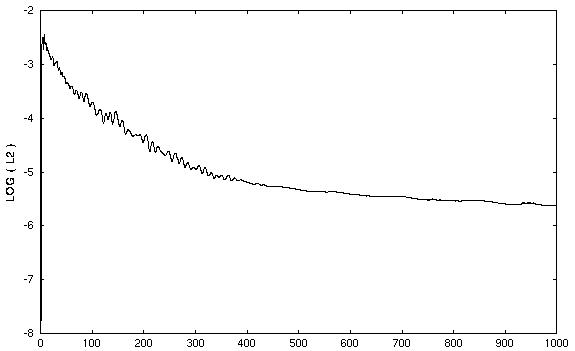
Figure 2. Plot of the L2 solution residual history.
A more significant indicator of solution convergence is to examine the convergence of the engineering quantity to be obtained from the analysis. Here it is lift and drag on the airfoil. The loads keyword in the input data file raetaf.dat output this information into the list file raetaf.lis. RESPLT is used to read this information and create plot files,
resplt < resplt.liftconv.com
The file resplt.liftconv.com is a command file containing the inputs for RESPLT to output the GENPLOT formatted plot data file named liftconv.gen of the residuals as a function of the iterations. This file can be plotted using CFPOST,
cfpost < cfpost.liftconv.com
where the file cfpost.liftconv.com is a command file containing the inputs for CFPOST. CFPOST will display in sequence the plots for drag, lift, and z-direction force. Fig. 4 and 5 shows the convergence of the drag and lift as displayed by CFPOST.
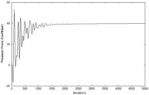
Figure 3. Plot of the sectional lift on the airfoil
with iterations.
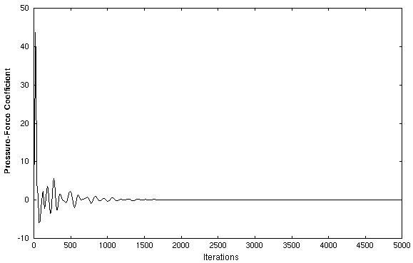
Figure 4. Plot of the sectional drag on the airfoil
with iterations.
The CFPOST utility can be used to generate engineering information from the the data files. First, Mach contours are generated with plot shown in Fig. 1.
cfpost < cfpost.mach.com
The verification aspect of this study involves examining if the integrated drag is zero. This information is obtained using CFPOST through an integration of the pressure forces on the airfoil,
cfpost < cfpost.forces.com
where cfpost.forces.com is the command input file for CFPOST. A list file named forces.lis is created in which the force information is printed.
From the file forces.lis, one sees that the total integrated drag is 3.76028E-02 lbf, which is essentially zero.
No sensitivity studies were performed. A grid convergence study should be performed to check if the drag asymptotically approaches zero as the grid size is reduced.
The computations were performed on a Silicon Graphics Octane workstation using 1 300 MHZ IP30 MIPS R12000 Processor. 1000 cycles for 5000 iterations required 1801.85 CPU seconds over an elapsed time of 2801.10 seconds.
1. Cook, P.H., M.A. McDonald, M.C.P. Firmin, "Aerofoil RAE 2822 - Pressure Distributions, and Boundary Layer and Wake Measurements," Experimental Data Base for Computer Program Assessment, AGARD Report AR 138, 1979.
This study was created on January 7, 2000 by,
John W. Slater
NASA John H. Glenn Research Center, MS 86-7
21000 Brookpark Road
Cleveland, Ohio 44135
Phone: (216) 433-8513
e-mail: John.W.Slater@grc.nasa.gov