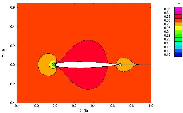
Figure 1. Mach contours at symmetry plane for ONERA M6 wing at Mach 0.3 and zero angle-of-attack with inviscid flow.
Figure 1. Mach contours at symmetry plane for ONERA M6 wing
at Mach 0.3 and zero angle-of-attack with inviscid flow.
This study is a verification study that examines the ONERA M6 wing at a lower Mach number of 0.3 and at zero angle-of-attack. Since the airfoil shape is symmetric with respect to the chord and has no camber, then for a shock-free, inviscid flow, there should be no lift and no drag as the pressure forces acting on the wing cancel.
Most of the files for this study are available in the Unix compressed tar file m6wing02.tar.Z. The files can then be extracted by the unix command
uncompress -c m6wing02.tar.Z | tar xvof -
The files m6wing.cgd, m6wing.cfl, m6wing.lis are not included in the tar file in order to limit the size of the tar file. They can be downloaded separately.
The grid and boundary conditions are identical to those of Study #1 and are not discussed here. The commond grid file is m6wing.cgd.
The initial flow conditions are simply the freestream flow values as presented in Table 2.
| Mach | Pressure (psia) | Temperature (R) | Angle-of-Attack (deg) | Angle-of-Sideslip (deg) |
|---|---|---|---|---|
| 0.3 | 14.7 | 460.0 | 0.0 | 0.0 |
The computation is performed using the time-marching capabilities of WIND to march to a steady-state (time asymptotic) solution. Local time stepping is used at each iteration. The time-marching is performed until convergence criteria is achieved.
The WIND input data file for this case is m6wing.dat. The freestream keyword indicates that the static freestream flow conditions are specified as Mach number, pressure (psia), temperature (R), angle-of-attack (degrees), and angle-of-sideslip (degrees). The turbulence model keyword indicates that inviscid flow is to be assumed. The implicit boundary on keyword indicates that implicit boundary conditions are used at the viscous wall boundaries. The downstream pressure keyword indicates that the freestream pressure is imposed on the outflow boundaries specified with a OUTFLOW bounary condition. The loads keyword indicates that the lift on the wing is to be integrated every 10 iterations and displayed in the list file. This will we used to evaluate the convergence of the solution. The cycles keyword indicates that a maximum of 1500 cycles will be run. The iterations per cycle keyword indicates that 5 iterations will be run per cycle. The cfl# keyword indicates that a CFL number of 2.0 is used. By default, WIND uses local maximum allowable time-step based on the specified CFL number. The converge order keyword indicates that the computation will stop if the L2 norm of the solution drops by 5 orders-of-magnitude.
The WIND solver was run by entering
wind -runinplace -dat m6wing -mp -parallel
The final solution was written to the solution data file m6wing.cfl. The computation and convergence information was written to the output list file m6wing.lis.
There are several ways to examine the convergence of the solution. The RESPLT utility is used for these to read information from the list file m6wing.lis. First the L2 norm of the residual of the conservation variables (change over a time step) can be read from the list file,
resplt < resplt.nsl2.com
The file resplt.nsl2.com is a command file containing the inputs for RESPLT to output the GENPLOT formatted plot data file named nsl2.gen of the residuals as a function of the number of iterations. This file can be plotted using CFPOST,
cfpost < cfpost.nsl2.com
where the file cfpost.nsl2.com is a command file containing the inputs for CFPOST. Fig. 3 shows the solution residual that is displayed by CFPOST.
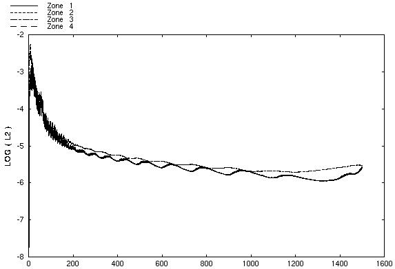
Figure 3. Plot of the L2 solution residual history -vs- cycles.
The CFPOST utility can be used to generate and plot flow contours at a cutting plane perpendicular to the wing span. Here the Mach number contours are generated and plotted at section 1 (y/b=0.01), which is shown in Fig. 1. Note the symmetry of the countour lines, indicating that the flow is symmetric about the top and bottom surfaces.
cfpost < cfpost.zcut.mach.com
This verification expects the integrated pressure lift and drag over the wing to be zero. CFPOST can be used to integrate these forces over the surface of the wing,
cfpost < cfpost.forces.com
where cfpost.forces.com is the command input file for CFPOST. A list file named forces.lis is created in which the force information is printed.
Examining the file forces.lis, one can see that the total lift on the wing is -4.52087E-04 lbf and the total drag is 3.58686E-03 lbf, which are essentially zero.
No sensitivity studies were performed. A grid convergence study should be performed with finer grids to examine if the total lift and drag approach zero in the asymptote of smaller grid spacing.
The computations were performed on a Silicon Graphics Octane workstation using 2 300 MHZ IP30 MIPS R12000 Processors. 1500 cycles for 7500 iterations required 48025.68 CPU seconds over an elapsed time of 25028.89 seconds.
Schmitt, V. and F. Charpin, "Pressure Distributions on the ONERA-M6-Wing at Transonic Mach Numbers," Experimental Data Base for Computer Program Assessment. Report of the Fluid Dynamics Panel Working Group 04, AGARD AR 138, May 1979.
This study was created on January 7, 2000 by John W. Slater, who may be contacted at
NASA John H. Glenn Research Center, MS 86-7
21000 Brookpark Road
Cleveland, Ohio 44135
Phone: (216) 433-8513
e-mail: John.W.Slater@grc.nasa.gov