
|
4-Stroke Internal Combustion Engine
|
Glenn
Research
Center
|
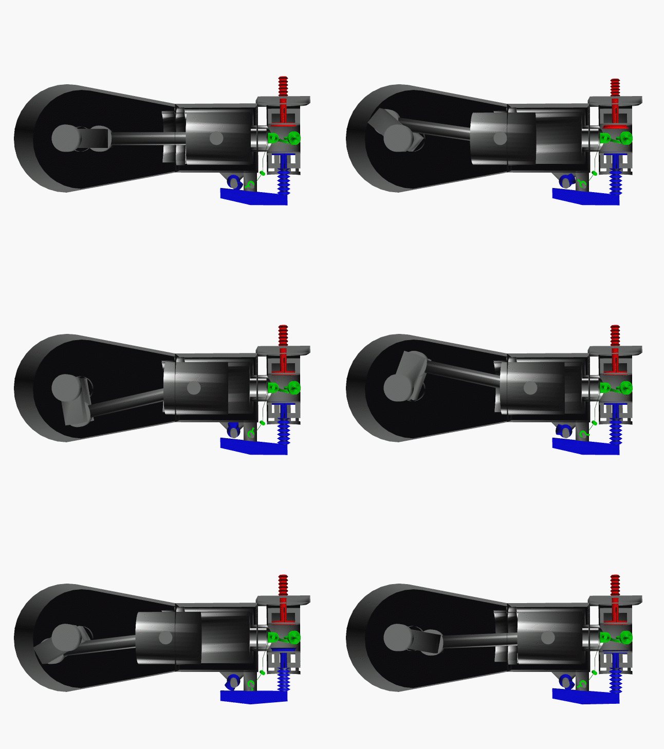
This is an animated computer drawing of one cylinder of the Wright
brothers' 1903 aircraft engine.
This engine powered the first, heavier than
air, self-propelled, maneuverable, piloted aircraft; the Wright
1903 Flyer.
The engine consisted of four
cylinders
like the one shown above, with
each piston connected to a common
crankshaft.
The crankshaft was connected to two counter-rotating
propellers
which produced the
thrust necessary to overcome the
drag of the aircraft.
The brothers' design is very simple by today's standards, so it is a good
engine for students to study to learn the fundamentals of
engine operation. This type of
internal combustion
engine is called a
four-stroke engine because there are four movements, or
strokes,
of the piston before the entire engine firing sequence is repeated.
The four strokes are described below with some still figures.
In the animation and in all the figures, we have colored the
fuel/air intake system
red, the
electrical system
green, and the
exhaust system
blue. We also represent the fuel/air mixture and the exhaust gases by small
colored balls to show how these gases move through the engine.
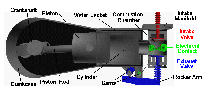
Since we will be referring to the movement of various engine parts, here is
a figure showing the names of the parts:
Intake Stroke
The engine
cycle
begins with the
intake stroke
as the piston is
pulled towards the crankshaft (to the left in the figure).
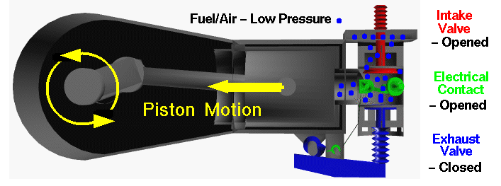
The intake valve is open, and fuel and air are drawn past the valve
and into the combustion chamber and cylinder
from the intake manifold located on top of the combustion chamber.
The exhaust valve is closed and the electrical contact switch is open.
The fuel/air mixture is at a relatively low
pressure
(near atmospheric)
and is colored blue in this figure. At the end of the intake stroke, the
piston is located at the far left and begins to move back towards the
right.
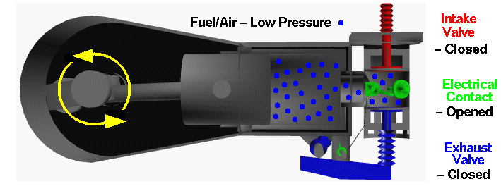
The cylinder and combustion chamber are full of the low pressure fuel/air mixture
and, as the piston begins to move to the right, the intake valve closes.
Historical note -
The opening and closing of the intake valve of the Wright 1903 engine
was termed "automatic" by the brothers. It relies on the slightly lower pressure within
in the cylinder during the intake stroke to overcome the strength
of the spring holding the valve shut. Modern internal combustion engines do
not work this way, but use cams and rocker arms like the brothers' exhaust system.
Cams and rocker arms provide better control and timing of the opening and
closing of the valves.
Compression Stroke
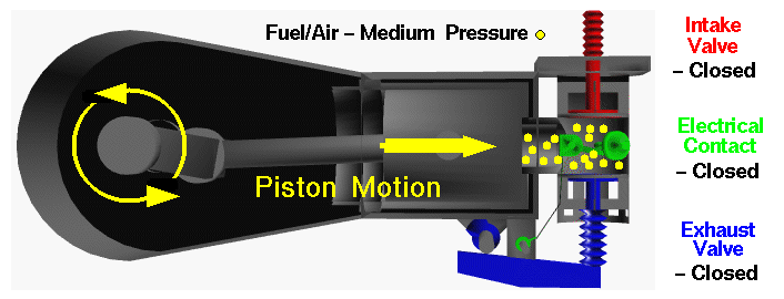
With both valves closed, the combination of the cylinder and combustion chamber
form a completely closed vessel containing the fuel/air mixture. As the piston
is pushed to the right, the volume is reduced and the fuel/air mixture is
compressed during the
compression stroke.
During the compression, no
heat
is transferred to the fuel/air mixture.
As the volume is decreased because of the piston's motion,
the pressure in the gas is
increased, as described by the laws of
thermodynamics.
In the figure, the mixture has been colored
yellow to denote a moderate increase in pressure.
To produce the increased pressure, we have to do
work
on the mixture, just
as you have to do work to inflate a bicycle tire using a pump.
During the compression stroke, the electrical contact is kept opened.
When the volume is the smallest,
and the pressure the highest as shown in the figure, the contact is closed, and
a current of
electricity flows through the plug.
Power Stroke
At the beginning of the power stroke, the electrical contact is opened.
The sudden opening of the contact produces a spark in the combustion chamber which
ignites the fuel/air mixture. Rapid
combustion
of the fuel releases
heat,
and produces exhaust gases in the combustion chamber.
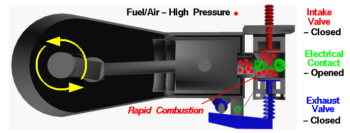
Because the intake and exhaust valves are closed, the combustion of the
fuel takes place in a totally enclosed (and nearly constant volume) vessel. The
combustion increases the
temperature
of the exhaust gases, any residual air
in the combustion chamber, and the combustion chamber itself. From the
ideal gas law,
the increased temperature of the gases also produces an increased
pressure in the combustion chamber. We have colored the gases red in the figure
to denote the high pressure. The high pressure of the gases acting on the
face of the piston cause the piston to move to the left which initiates the
power stroke.
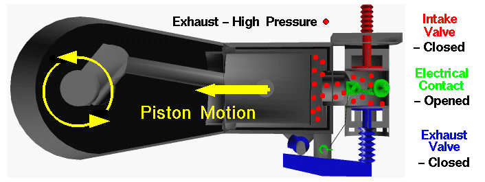
Unlike the compression stroke, the hot gas does work on the piston during the power stroke. The force
on the piston is transmitted by the piston rod to the crankshaft, where the linear
motion of the piston is converted to angular motion of the crankshaft. The work
done on the piston is then used to turn the shaft, and the propellers, and
to compress the gases in the neighboring cylinder's compression stroke. Having
produced the igniting spark, the electrical contact remains opened.
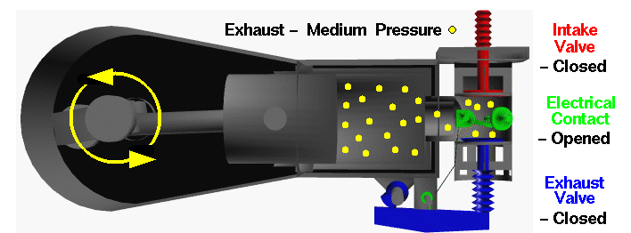
During the power stroke, the volume occupied by the gases
is increased because of the piston motion and no
heat
is transferred to the fuel/air mixture.
As the volume is increased because of the piston's motion,
the pressure and temperature of the gas are
decreased.
We have colored the exhaust "molecules" yellow to denote a moderate amount of pressure
at the end of the power stroke.
Historical note - The method of producing the electrical spark
used by the Wright brothers is called a "make and break" connection. There
are moving parts located inside the combustion chamber. Modern internal combustion
engines do not use this method, but instead use a spark plug to produce the
ignition spark. A spark plug has no moving parts, which is much safer than the
method used by the brothers.
Exhaust Stroke
At the end of the power stroke, the piston is located at the far left. Heat that
is left over from the power stroke is now
transferred
to the water in the
water jacket
until the pressure approaches atmospheric
pressure. The exhaust valve is then opened
by the cam pushing on the rocker arm to begin the
exhaust stroke.
The purpose of the exhaust
stroke is to clear the cylinder of the spent exhaust in preparation for another
ignition cycle.
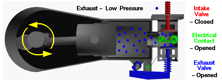
As the exhaust stroke begins, the cylinder and combustion chamber are full
of exhaust products at low pressure (colored blue on the figure above.)
Because the exhaust valve
is open, the exhaust gas is pushed past the valve and exits the engine.
The intake valve is closed and the electrical
contact is open during this movement of the piston.
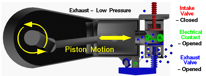
At the end of the exhaust stroke, the exhaust valve is closed and the engine
begins another intake stroke.
Historical note - The exhaust system used by the Wright brothers
caused the hot exhaust to exit each cylinder independently ... right next
to the pilot. This engine was very loud as well. Modern automobiles collect
the exhaust from all of the cylinders into an exhaust manifold (just like the
intake manifold used by the brothers). The exhaust manifold passes the
exhaust to the catalytic converter to remove dangerous gases, and then through
the muffler to keep it quiet, and finally out the exhaust pipe.
You should now be able to make some sense from
the animation at the top of this page. Notice that the crankshaft makes two
revolutions for every one revolution of the cams. This motion is controlled by the
timing chain. Also notice how the cam moves the exhaust valve
at just the right time and how quickly the intake valve opens after the exhaust
valve is closed. In real engine operation, the exhaust stroke can not push all of
the exhaust out of the cylinder, so a real engine doesn't perform as well as the
ideal engine described on this page. As the engine runs and heats up, the performance
changes. Modern automobile engines adjust the fuel/air ratio with computer controlled
fuel injectors to maintain high performance. The brothers just had to watch the
horsepower of their engine drop from about 16 horsepower when the engine was
first started to about 12 horsepower when it was running hot.
Activities:
Guided Tours
Navigation ..


- Beginner's Guide Home Page
|
