Mathematics and science were invented by humans to describe and
understand the world around us.
We live in a world that is defined by three spatial dimensions and one
time dimension. Objects move within this domain in two ways.
An object
translates,
or changes location, from one
point to another.
And an object
rotates,
or changes its orientation.
In general, the motion of an object
involves both
translations
in all three directions and
rotation
about
three principle axes.
On this page we are going to simplify the discussion and
neglect changes in time and one of the spatial dimensions.
So we will only consider motion in a two-dimensional plane. At the
bottom of the page we include some comments about extending these ideas to
three dimensions.
To describe the motion of an object, we need to locate the object relative to some
reference location. We will call the reference location the origin.
We need two pieces of information to describe the location because
the plane is two dimensional.
There are many ways to specify the location of a point p
relative to the origin. We will discuss two ways of making the determination.
One way to specify the location of point p is to define two
perpendicular coordinate axes through the origin. Each axis is a number line, with
a length increment selected along the line. On the figure,
we have labeled these axes X and Y and the resulting coordinate system
is called a rectangular or Cartesian coordinate system.
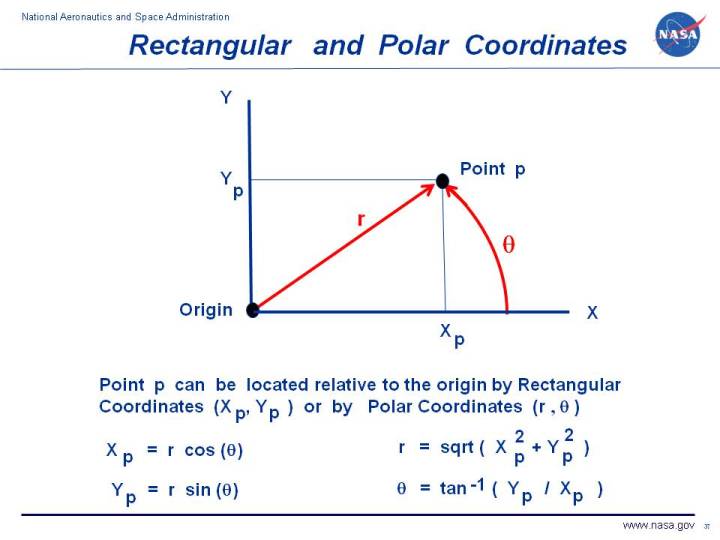
To determine the location of point p we measure out from the Y
axis, parallel to the X axis, to obtain a distance Xp. And then we measure up from
the X axis, parallel to the Y axis to obtain Yp. The pair of coordinates
(Xp, Yp) describe the location of point p relative to the origin.
The system is called rectangular
because the angle formed by the axes at the origin is 90 degrees and the angle formed by
the measurements at point p is also 90 degrees. So the measurment forms a rectangle
with sides Xp and Yp.
The system is called Cartesian because it was extensively used by the French mathematican
Rene Descartes.
Another way to specify the location of point p would be to directly measure the
distance r between the origin and point p. But we need another piece of information.
There are an infinite number of points that are a distance r away from the origin.
They form a circle around the origin with radius r. To specify the location of point p,
we can pick a reference line that goes through the origin and measure the angle theta
formed by the reference line and a line going through point p. On the figure, we
have made the reference line lie right along the Cartesian X axis. The coordinate pair
(r, theta) uniquely describe the location of point p. This set of coordinates
is called a polar coordinate system. You will notice on the figure that the angular measurement
theta crosses the radial measurement r by forming a 90 degree angle at point p.
So a polar coordinate system is said to be an orthogonal coordinate system, just like the
rectangular system.
The location of point p relative to the origin is the same in any coordinate system. We just
describe that location differently depending on the coordiante system that we use. For the two
orthogonal coordinate systems that we are considering, we can define functions that let us switch
between the two descriptions. If we have determined the location of point p by the polar
coordinate system (r, theta), we can find the rectangular coordinates (Xp, Yp) by these
equations:
Xp = r cos (theta)
Yp = r sin (theta)
where sin and cos are the
trigonometric sine and cosine functions. Likewise, if we know the rectangular
coordinates, we can determine the polar coordinates by these equations:
r = sqrt (Xp^2 + Yp^2)
theta = tan^-1 (Yp / Xp)
where sqrt is the square root
function and tan^-1 is the inverse
tangent or arc tangent
function.
On this slide, for simplicity, we have developed the
coordinate equations in only two dimensions which requires two coordinate axes.
For aircraft and rocket motion, there are three spatial dimensions and
therefore three coordinates required.
For rectangular coordinates, we can simply add a third axis Z that is perpendicular
to both X and Y. This addition produces a rectangular Cartesian coordinate
system consisting of X, Y, and Z.
For polar coordinates, there are several different possibilities for describing the
third dimension. We could add another axis Z that is perpendicular to the plane formed
by r and theta. This addition produces a cylindrical coordinate system consisting
of r. Z and theta. Or we could specify another angle phi that is
perpendicular to the radius r and the angle theta. This addition produces a
spherical coordinate system consisting of r, theta and phi. There are
conversion equations that let you switch between any of these coordinate systems.
There is a whole branch of mathematics called
tensor analysis
that deals with the
subject of coordinate systems and how to convert between various coordinate systems.
This subject becomes very important when we get into the details of calculus and how
the values of variables change within a given coordinate system.
The choice of coordinate system is often dictated by the geometry of a particular problem. For example,
the surface of a tube is more easily described by a cylindrical coordinate system
than by a spherical or rectangular coordinate system. It can be done with any three dimensional
coordinate system, but the geometry favors the cylindrical in this case.
Activities:
Guided Tours
Navigation ..


- Beginner's Guide Home Page
|