During the fall of 1901, the brothers began to question the aerodynamic
data on which they were basing their aircraft designs.
They decided to
conduct a series of
wind tunnel tests
to verify the results they were
experiencing
in flight.
They would measure the aerodynamic lift and drag
on small
models
of their wing designs using a
wind tunnel
in their bicycle shop in Dayton, Ohio.
They built two separate balances to perform these measurements,
one for
lift.
and the other for
drag.
On this page we will discuss
the operation of the drag balance.
On the drag balance, they measured the ratio of the
drag of the model to the lift of the model. Then, knowing the lift
from the lift balance, they could determine the drag of model.
The operation of the balance depends on the concepts of
torques
and
equilibrium.
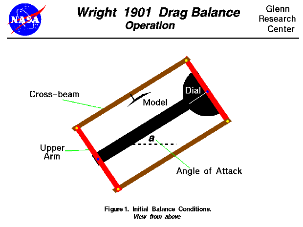
As the test begins, the tunnel is turned off and a model is
placed on the cross beam of the balance. The
angle of attack
of the model is set by rotating the balance on the mounting screw
as shown in the figure at the top of this page.
The brothers had inscribed lines on the floor of the tunnel to
accurately determine the amount of rotation.
In this drawing, we are using the same color scheme as used on the page
describing the
design
of the drag balance and
we are looking down onto the balance from above.
The fan which pushes air through the tunnel is far to the right of this drawing.
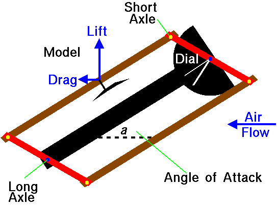
When the fan is turned on, the cross beams and arms move because of torques
generated by the lift and drag force of the
model on the long axles.
When the torque created by the drag of the model is
balanced by the torque generated by the lift of the model, the
balance no longer moves and assumes the following orientation:

On this figure we show the direction of the forces by the small arrows on the
model.
The forces generated by the model are transmitted to the arms through the
short axles.
The arms transmit the force to the long axle and eventually to the frame and
tunnel walls. As the arms rotate because of the torque, the pointer of the dial
rotates as well. The pointer is always perpendicular to the arm.
The torque about a point on an object is equal to the force applied to the object times
the perpendicular distance from the point to the place where the force is
applied.
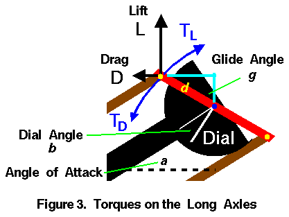
This figure shows the magnitude and orientation of the torques on the long axles.

The length of the arm is given by the symbol d and the
arm forms an angle g with a vertical line in the figure.
The Wrights called this angle the glide angle.
The drag force (D) generates a torque (TD) in the counter-clockwise
direction.
The distance from the long axle measured perpendicular to the
model drag force is d times the
cosine
of the angle g.
The torque (TD) is then given by:
TD = D * d * cos(g)
The lift force (L) generates a torque (TL) in the clockwise
direction.
The distance from the long axle measured perpendicular to the
model lift force is d times the
sine
of the angle g.
The torque (TL) is then given by:
TL = L * d * sin(g)
In equilibrium, these torques are equal and the long axle does not rotate.
TD = TL
D * d * cos(g) = L * d * sin(g)
D = L * sin(g) / cos(g)
The sine divided by the cosine is equal to the
tangent
of an angle. Then:
D = L * tan(g)
We can get mathematical relations for the lift of the model from the
lift equation.
L= k * V^2 * A * cl
where k is the
Smeaton coefficient,
V is the velocity, A is the surface area of the model,
and cl is the lift coefficient.
Similarly, the
drag equation is:
D= k * V^2 * A * cd
where cd is the drag coefficient.
Substituting into the torque equilibrium equation:
k * V^2 * A * cd = k * V^2 * A * cl * tan(g)
cd / cl = tan(g)
If you compare this equation with the equation for the
flight angle
of a
descending glider,
you will see that the angle g is the glide angle
experienced in flight.
By carefully studying the diagram and using
an equation
from geometry,
we find that the glide angle g
is equal to the angle of attack a plus
the angle b recorded on the dial.
g = a + b
The angle b is called the tangential angle.
The ratio of the forces along and perpendicular to the cross beam
is equal to the tangent of the angle b.
Knowing the angle of attack of the model,
the Wrights could determine the drag coefficient by
recording the angle on the dial, adding the angle of attack,
getting the lift coefficient from a previous test and solving the
equation given above for cd.
They repeated the test process many times, changing models and angle of attack
of the models to generate graphs of their results.
You can do the same thing, on-line, with an interactive
computer simulation
of the tunnel and balance which we have developed.
Navigation..


- Beginner's Guide Home Page
|
