Aerodynamicists use
wind tunnels
to test
models
of proposed aircraft and engine components.
During a test, the model is placed in the
test section
of the tunnel and air is made to flow past the model.
Various types
of instrumentation are used during the test to determine the
forces
on the model and to better understand the movement of air around
and through the model.
Diagnostic testing to increase our understanding of
flow phenomenon is the subject of this web page.
Diagnostic instrumentation includes
static pressure taps,
total pressure rakes,
laser Doppler velocimetry,
laser sheets,
and
hot-wire
velocity probes.
A diagnostic test does not determine the forces on the aircaft, but helps the
engineer to better understand how the fluid moves around and through the model. There are
a variety of flow control devices that are employed to improve
performance of the aircraft, if the local flow conditions are known.
Depending on the type of instrumentation used in the experiment,
steady state flow or unsteady, time-varying, flow information can be obtained.
The engineer must use some experience when employing flow
diagnostic instrumentation to properly place the instruments in regions of flow gradients
or separations.
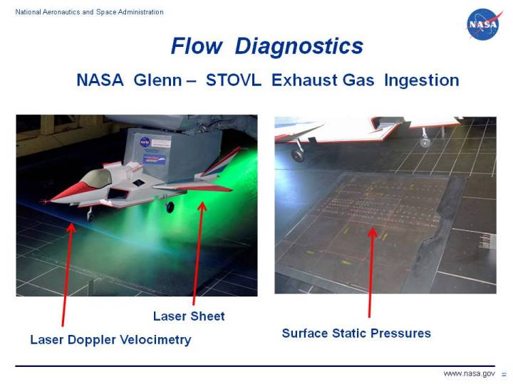
On the slide, we see three examples of flow diagnostics used to determine the
flow of air around a short take-off vertical landing (STOVL) aircraft model.
During low speed flight near the ground, the exhaust from the
jet engine
is used to counteract
the weight of the aircraft. But as the gas exhaust strikes the ground, it can be swept up
and re-ingested through the
aircraft inlet.
The hot gas becomes a source of
inlet distortion
which can cause the engine to loose power.
On the left of the figure we see a green laser sheet that is used to visualize the
flow plume that forms between the jet exhausts. The blue beam from the left is
part of a laser doppler system to measure the velocity of the plume. On the right of the
figure we see a grid of static pressure taps on the tunnel floor to map the flow beneath the model.
During the test, but not shown here, colored oil streaks were also used to determine flow directions.
The tunnel was run at very low velocity to determine how local winds affects gas ingestion.
Navigation ..

- Beginner's Guide Home Page
|